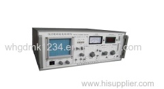
Portable Partial Discharge Test
| Min. Order: | 1 Set/Sets |
|---|---|
| Trade Term: | FOB, |
| Payment Terms: | T/T |
| Supply Ability: | 10 |
| Place of Origin: | Hubei |
Company Profile
| Location: | Wuhan, Hubei, China (Mainland) |
|---|---|
| Business Type: | Manufacturer |
Product Detail
| Model No.: | TKJF |
|---|---|
| Measure channel: | 4-channel |
| Capacitance range of measured piece: | 6pF~250uF |
| Production Capacity: | 10 |
Product Description
Product Introduction
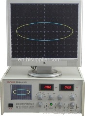
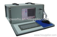
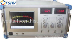
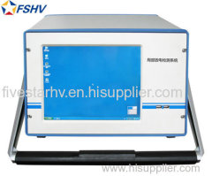
TKJF fit for many products it has high sensitivity high S/N a large screen which has clear testing wave displaying high frequency ellipse scan (the power is less than 1VA). auxiliary zero marking system. The discharge meter has pointer/digital display and linearity /digital function. The amplifier has large dynamic range 9 kinds of frequency band combinations.
TKJF is a powerful tool for developing new high voltage electric products and improving the quality of the products. It is also an efficient testing device to judge the work condition of equipments on the work field. This device is used together with model JZF-9 or JZF-10 calibrator.
product features Product Characteristics
Working Principle
When measured piece Cx has partial discharge under testing voltage the circuit will have pulse current which get by the input unit. The pulse signal is amplified by front amplifier and the frequency band is chose by filter amplifier then been amplified to needed amplitude by the main amplifier. The pulse signal will be displayed on oscillograph screen. The pulse value is also sent to the pulse peak meter and displayed immediately. The time window unit chooses a working period of the pulse peak meter during each cycle of testing voltage and it increases the brightness of the relevant displaying area in this time. In this way it can avoid the disturbing of fixed phase.
Input discharge volume to the measured piece Cx through JZF series PD external calibrator adjust the fine adjusting knob till the displayed value is equal to the discharge volume the discharge can be read directly and conveniently on the meter without counting.
The testing voltmeter will have an over zero mark signal of testing voltage through the voltmeter resistance R and the zero mark pulse will be displayed on oscillograph screen. The testing voltage can be displayed on KV meter.
Product Parameters
Technical Parameters
Main specification
1 Measure channel:4-channel
2 Capacitance range of measured piece 6pF~250uF
3 Measuring sensitivity and Max. current(see table 1)
Table 1.
No. | Tuning capacitance range | Sensitivity (pC) (Un-balance circuit) | RMS of max. current
| |
(Un-balance circuit) | (Balance circuit) | |||
1 | 0~25~100pF | 0.02 | 30mA | 0.25A |
2 | 25~100~400pF | 0.04 | 50mA | 0.5A |
3 | 100~400~1500pF | 0.06 | 120mA | 1A |
4 | 400~1500~6000pF | 0.1 | 0.25A | 2A |
5 | 1500~6000~25000pF | 0.2 | 0.5A | 4A |
6 | 0.006~0.025~0.1uF | 0.3 | 1A | 8A |
7 | 0.025~0.1~0.4uF | 0.5 | 2A | 15A |
8 | 0.1~0.4~1.5uF | 1 | 4A | 30A |
9 | 0.4~1.5~6.0uF | 1.5 | 8A | 60A |
10 | 1.5~6.0~25uF | 2.5 | 15A | 120A |
11 | 6.0~25~60uF | 5 | 25A | 200A |
12 | 25~60~250uF | 10 | 50A | 300 A |
7R | Resistor | 0.5 | 2A | 15A |
4 Time base of ellipse scan
(1) Frequency 50 /60(inner) 100 150 200 400Hz
(2) Turn: 30º per grade total 360º
(3) display ways: ellipse_expand_beeline
(4) The high frequency time base ellipse can be adjusted to normal state by input voltage (10-250V) and the power is less than 1 VA. Auto-protecting function when overload
5 Displaying Unit
A rectangle oscillograph tube (124×104mm²) which has brightness and focus knobs.
6 Amplifier
(1) On low frequency 3dB fL: 10 20 40 KHz optional
(2) On high frequency 3dB fH: 80 200 300 KHz optional
(3) Gain adjusting: 6 grades of gross adjustment. Gain difference between grades is 20±1dB fine adjusting range >20dB
(4) Asymmetry of plus and minus pulse responding < 1dB
7 Time window
(1) Adjustable window width 15º~150º on 50/60Hz
(2) Rotatable window position 0º~170º
(3)Two windows can on/off respectively or simultaneously
8 Pulse peak meter
(1) Pointer meter with linear graduation. 0-100
(2) Pointer meter with logarithm graduation. 0-10-100
(3) Digital meter with 3.5 bits LED digital display 0-100
(4) Discharge magnitude linear deviation: <±10%
9 Zero mark system
(1) Made by inner zero mark generator it can change polarity and rotate 0-180º so it can correspond with the true zero mark which is made by high voltage resistor.
(2) The zero mark is corresponded with all ellipse scan frequency.
10 Power
AC Power: 230/400V; 60Hz; 3Phase
11 Work environment
Vicinity medium temperature is -5 ºC ~+45ºC
Air relative humidity is no more than 85%


