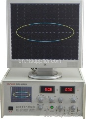
Partial Discharge Test Set
| Min. Order: | 1 Set/Sets |
|---|---|
| Payment Terms: | T/T |
| Place of Origin: | Hubei |
Company Profile
| Location: | China (Mainland) |
|---|---|
| Business Type: | Manufacturer, Distributor/Wholesaler |
| Main Products: | Resistance Tester, Transformer Turn Ratio Tester, High Voltage Testing, Electrical Test Equipment, Very Low Frequency HV Tester VLF |
Product Detail
| Means of Transport: | Ocean |
|---|
Product Description
Product Description
1 General
DTTW series of Power-frequency Partial-discharge Test Set are integrated equipments of Voltage Withstand test and Partial-discharge Detection. They are intended to test partial discharge of electrical products, but also they are very capable to perform withstand voltage test.
The system includes:
1). DTZY-xx/xx Automatic Control Unit within Voltage Regulator.
2). DTLB-xx/xx Noise Filter.
3). DTTW-xx/xx No-partial-discharge HV Test Transformer.
4). DTRW-xx/xx Protective Resistor.
5). DTFW-xx/xx Capacitive Voltage Divider
And Coupling Capacitor.
6). DTJR-1/7 Partial-discharge Input Unit.
7). DTJF-2008 Partial-discharge Detector.
8). DTJJ-99 Partial-discharge Calibrator.
9). A set of related Accessories.
Protective Resistor
HV Test Transformer
Coupling Capacitor
Divider Capacitor
Noise Filter Auto Control Unit PD Detector
2 DTZY AC High Voltage Test Set
2.1 Features
Program-controlled HV regulating.
Auto/Manual operating mode.
Voltage, Current, Time can be set freely.
Refuse to up HV when reach the customized Max. HV.
Auto Timing at Goal HV, Auto Regulating down to bottom when Time up.
Auto cut off HV when over the preset Goal HV or HV Current or LV Current, and then Auto Regulate down to bottom, and give sound-light alarm.
Auto Capture Peak Voltage when break down.
Auto/Manual Printing Mode
Zero start high voltage safety interlock.
External safety interlock for door control or infrared detector.
Emergency-stop push-button for accident.
Optional RS-232/485 port to Computer.
2.2 Technical Data
Power Supply: Three-phase Five-wire, 380V± 10%, 50Hz± 1
Rated Voltage: Customized (kV)
Rated Current: Customized (mA)
Rated Power: Customized (kVA)
High Voltage Resolution: Min 0.01kV
HV-side Current Resolution: Min 0.01mA
LV-side Current Resolution: Min 0.01A
Measuring Accuracy: Less than 1%
Time range: 0~9999S
Ambient Temperature: 0~40° C
Ambient Humidity: ≤ 80%RH
Absolute Altitude: ≤ 1000m
3 DTJF-2008 Partial Discharge Detector
3.1 Technical Data
3.1.1 Capacitance range: 6pF~250μ F
3.1.2 Amplifier bands
1) Low Frequency: 10 kHz, 20 kHz, 40 kHz selectable
2) High Frequency: 80 kHz, 200 kHz, 300 kHz selectable
3.1.3 Amplifier gain adjustment
Coarse adjustment: 6 scales, every 20± 1dB
Fine adjustment: ≥ 20 dB
3.1.4 Time windows (Blue)
1) Width: 15° ~150° Adjustable
2) Position: 0° ~170° Adjustable
3) Two windows can be opened simultaneously or separately.
3.1.5 Ellipse time base (Yellow)
1) Frequency: 50Hz or any frequency
2) Rotation: 180° Range, each step 30o
3) Display mode: Ellipse / straight line
4) High-frequency time-base input-voltage less than 220V
3.1.6 Have Internal / External Zero marker
3.1.7 Waveform Locking
Push button to lock waveform at any time, to help observation and analysis.
3.1.8 PD meter
1) Range: 0~100.0 PC
2) Accuracy: Less than 5%
3.1.9 HV meter
1) Range: 0~100.0 kV
2) Accuracy: Less than 5%

