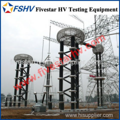
Impulse Voltage Generating Test System
| Min. Order: | 1 Set/Sets |
|---|---|
| Trade Term: | FOB,CFR,CIF,EXW |
| Payment Terms: | L/C, T/T |
| Supply Ability: | 100 per year |
| Place of Origin: | Hubei |
Company Profile
| Location: | Wuhan, Hubei, China (Mainland) |
|---|---|
| Business Type: | Manufacturer, Trading Company |
| Main Products: | Resonant Test System, Dielectric Strength Test Set |
Product Detail
| Model No.: | SXCF |
|---|---|
| Means of Transport: | Ocean, Air, Land |
| Brand Name: | Sansionpower |
| Production Capacity: | 100 per year |
| Packing: | Plywood case |
| Delivery Date: | 15-30 working days |
Product Description
Main Parameters for System:
♦ Nominal voltage: 200kV/300kV/400kV/800kV or at customized
♦ Rated stage voltage: 100kV
♦ Rated stage energy: 2.5kJ
♦ Stage Impulse capacitance: 0.5µF
♦ Number of Stages: 2/3/4/8 stages at customized
♦ Impulse voltage waveform: generated when load capacitance is 300-3000pF.
T1=1.2µs±30%, T2=50µs±20%, standard lightning impulse voltage full waveform of peak voltage deviation≤3%;
Standard operation waveform 250 ± 20%/2500 ± 60%. These 2 impulse voltage waveform parameters and error are accorded with national requirements of GB311.1and GB16927.1 standard and IEC standard.
♦ Voltage utilization factor: Standard lightning impulse voltage waveform ≥90% when load capacitance is below 1000pF, standard operation impulse voltage waveform≥80% when load capacitance is below 2000pF. Standard operation impulse voltage waveform ≥70%.
♦ Locking range: level voltage is within the range of 20%-100%rated voltage, positive and negative locking range no less than 25%.
♦ Out-of-control rate of synchronous discharge: <5%
♦ Min.output voltage: ≥±20% of rated voltage.
♦ Instability of discharge voltage: <±1.0%
♦ Continuous time: Above 2/3 of rated voltage, continuous working when charge and discharge once every 120s. Below 2/3 of rated voltage, continuous working when charge and discharge once every 60s.
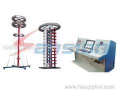
System Configuration:
1. Charging Device
♦ Constant current charging device, rated output voltage±100kV, rated output DC current 10-100mA.
♦ Oil type charging transformer, primary voltage is 220V, secondary voltage is 50kV, rated capacity is 5kVA. No oil leakage of transformer.
♦ 2DL-200kV/100mA HV rectifying silicon stack(HV diode), reverse voltage200kV, average current 0.1A. HV diode is installed on the charging board.
♦ Protective resistor of HV diode is made of enameled resistance wire.
♦ Instability of charging voltage <±1% at 15%-100%rated charging voltage of constant charging device. The adjustable accuracy of charging voltage is 1%.
♦ DC resistance voltage divider 100kV, 200mΩ, with HV vitreous glaze resistor. LV resistor is installed at the bottom of divider, while the voltage signal of LV side is lead to measurement system by shield cable.
♦ Automatic earth switch is open and close by electromagnet. Automatically short-circuit main capacitor and ground by protective resistor when testing stops.
♦ Charging transformer, HV silicon rectifier, resistance divider, charging current-limiting resistor and main controller are installed in the same movable chassis.
♦ Change the polarity automatically.
♦ The device is not only used as charging power supply of impulse voltage generat or, but also as DC voltage generator to generate 100kV DC voltage, which can b e used in DC test for other apparatus.