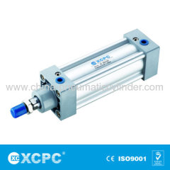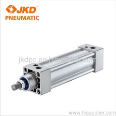
Air Cylinder
| Min. Order: | 50 Piece/Pieces |
|---|---|
| Payment Terms: | L/C, T/T |
| Supply Ability: | 1000 pcs per week |
| Place of Origin: | Zhejiang |
Company Profile
| Location: | Ningbo, Zhejiang, China (Mainland) |
|---|---|
| Business Type: | Manufacturer, Trading Company |
| Main Products: | Standard Cylinder, Standard Pneumatic Cylinder Accessories, Pneumatic Cylinder Kits, Festo Type Air Units, Festo Mini FRL |
Product Detail
| Model No.: | SI-50X100 |
|---|---|
| Means of Transport: | courier, Ocean, Air |
| Brand Name: | XCPC |
| Motion Pattern: | Double Action |
| Working Medium: | Air |
| Working Pressure Range: | 0.1~0.9MPa |
| Buffer Type: | Adjustable Buffer |
| Production Capacity: | 1000 pcs per week |
| Packing: | international standard,wooden boxes, pallets,cartons |
| Delivery Date: | 2-4 weeks |
Product Description
product name : Air Cylinder
Bore(mm) | 32 | 40 | 50 | 63 | 80 | 100 | 125 | 160 | 200 | 250 | 320 |
Motion Pattern | Double Action | ||||||||||
Working Medium | Air | ||||||||||
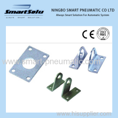
Fixed Type | Normal type FA/Type FB/Type CA/Type CB/Type SDB/Type LB/Type TC/Type | ||||||||||
Working Pressure Range | 0.1~0.9MPa | ||||||||||
Ensured Pressure Resistance | 1.35MPa | ||||||||||
Operating Temperature Range | -5~70℃ | ||||||||||
Operating Speed Range | 50~800mm/s | ||||||||||
Buffer Type | Adjustable Buffer | ||||||||||
Buffer Stroke | 24 | 32 | 42 | 33 | |||||||
Port Size | G1/8" | G1/4" | G3/8" | G1/2" | G3/4" | G1" | |||||
Air Cylinder Overall Dimensions 
dimension sheet Bore/Symbol A B C D E F G H I J K L M S T O 250 200 105 67 52 10 90 31 84 90 50 M42×2 M20 Φ30 270 220 G1" 320 218 120 82 52 10 110 31 96 110 63 M48×2 M24 Φ34 340 270 G1

Bore/Symbol | A | A1 | A2 | B | C | D | E | F | G | H | I | J | K | L |
32 | 142 | 190 | 187 | 48 | 94 | 30 | 28 | 16 | 27.5 | 22 | 17 | 6 | M10×1.25 | M6 |
40 | 159 | 213 | 207 | 54 | 105 | 35 | 32 | 18 | 29 | 24 | 19 | 7 | M12×1.25 | M6 |
50 | 175 | 244 | 233 | 69 | 105 | 40 | 42 | 25 | 30 | 32 | 24 | 8 | M16×1.5 | M8 |
63 | 190 | 259 | 250 | 69 | 120 | 40 | 40 | 24 | 31.5 | 32 | 24 | 8 | M16×1.5 | M8 |
80 | 214 | 300 | 286 | 86 | 128 | 40 | 53 | 30 | 35.5 | 40 | 30 | 10 | M20×1.5 | M10 |
100 | 229 | 320 | 308 | 91 | 138 | 45 | 55 | 32 | 36 | 40 | 30 | 10 | M20×1.5 | M10 |
125 | 279 | 398 | 372.5 | 119 | 160 | 60 | 74 | 45 | 46 | 54 | 41 | 13.5 | M27×2 | M12 |
160 | 332 | 484 | 448 | 152 | 180 | 65 | 94 | 58 | 50 | 72 | 55 | 18 | M36×2 | M16 |
200 | 337 | 514 | 472 | 157 | 180 | 75 | 100 | 57 | 50 | 72 | 55 | 18 | M36×2 | M16 |

Structure
NO. | Designation |
1 | Piston Rod Nut |
3 | Front cover seal ring |
5 | Bearing |
7 | Buffering O-Ring |
9 | Barrel |
11 | Wear Ring |
13 | Pistion O-Ring |
15 | Damping |
17 | Back cover |
NO. | Designation |
2 | Piston Rod |
4 | O-Ring |
6 | Front cover |
8 | Piston rod O-Ring |
10 | Piston |
12 | Magnet(Optional) |
14 | Pipe wall O-Ring |
16 | Hex socket screw |
Strock
Bore(mm) | Standard Stroke | Max.Stroke | Permissible Stroke |
32 | 25 50 75 80 100 125 160 175 200 250 300 350 400 450 500 | 1000 | 2000 |
40 | 25 50 75 80 100 125 160 175 200 250 300 350 400 450 500 600 700 800 | 1200 | 2000 |
50 | 25 50 75 80 100 125 160 175 200 250 300 350 400 450 500 600 700 800 900 1000 | 1200 | 2000 |
63 | 25 50 75 80 100 125 160 175 200 250 300 350 400 450 500 600 700 800 900 1000 | 1500 | 2000 |
80 | 25 50 75 80 100 125 160 175 200 250 300 350 400 450 500 600 700 800 900 1000 | 1500 | 2000 |
100 | 25 50 75 80 100 125 160 175 200 250 300 350 400 450 500 600 700 800 900 1000 | 1500 | 2000 |
125 | 25 50 75 80 100 125 160 175 200 250 300 350 400 450 500 600 700 800 900 1000 | 1500 | 2000 |
160 | 25 50 75 80 100 125 160 175 200 250 300 350 400 450 500 600 700 800 900 1000 | 1500 | 2000 |
200 | 25 50 75 80 100 125 160 175 200 250 300 350 400 450 500 600 700 800 900 1000 | 1500 | 2000 |
Cilinder theory output


.jpg)
.jpg)
.jpg)


