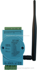
4-CH 0-10V NTC 10K 0-20mA input 2-ch 0-10V analog output 4-ch isolated digital output
| Min. Order: | 1 Piece/Pieces |
|---|---|
| Place of Origin: | Shanghai |
Company Profile
| Location: | Shanghai, China (Mainland) |
|---|---|
| Business Type: | Manufacturer |
| Main Products: | Analog Data Acquisition Modules, Ethernet 16channels 0-3V 0-4V 4-20mA Modbus-TCPIP Converter, Modbus RTU, Ethernet 16 Channels Normal Open Relay Output Modbus Tcpip, Analog Input Modules |
Product Detail
| Model No.: | S7108 |
|---|---|
| Brand Name: | SHJ Electronic Co., Ltd. |
Product Description
S7108 zigbee analog input, analog output, relay output PID control module is a high quality and low cost analog data acquisition module with one PID control. S7108 has total 4 channels input, 2 channels analog output and 4 channels isolated open-collector output . Each input has lightning and surge protection, the inputs can be any combination of 0-5V,0-10V,4-20mA,dry contact and NTC 10K thermistor. Analog output can output gradually through slew rate control and has default output when power up Output use RS485 or ZIGBEE wireless. Zigbee can realize the point-to-point, point-to-multipoint, multipoint-to-multipoint data transmission, can form a star, peer to peer and mesh network structure. Both of Rs485 and Zigbee using the industry standard Modbus protocol.
Highlights:
l Surge-protected analog inputs with 12-bit resolution and 100k sample speed ADC
l Input can be any combination of 0-10V,0-5V,4-20mA,NTC 10K thermistor and dry contact
l The analog input channel number is configurable, can be set up from 1 channel through 4 channel, improve sample rate for small count analog input
l Analog output can set power up output voltage and slew rate
l All outputs can be controlled by PID
l Any input can be set up link to PID
l Reliable Zigbee can up to 3000 meters communication
l Standard ModBus/RTU protocol allows for up to 254 unique devices on one network
l A lot of spare FLASH can be used to store user's parameters
l RS232 /RS485 or ZIGBEE for optional
l Can detect RS232/RS485 or ZIGBEE automatically, no need jumper
l You can tell us your requirement. we will update our firmware even after you received the modules ,you can update your modules through Zigbee or RS232/RS485 .
Application:
ü Remote data acquisition
ü Process monitoring
ü Industrial process control
ü Energy management
ü Supervisory control
ü Security systems
ü Laboratory automation
ü Building automation
ü Product testing
ü Direct digital control
Technical data:
Input Resolution--------------------------------------------------------------------------12-bit
Input channel number------------------------------------------------------------------------- 4
Input range----------------------------0~5V,0~10V,4~20mA,10K thermistor, dry contact
Input protection--------------------------------------------------------------Lightning, static
Accuracy-----------------------------------------------------------------------------------±0.1%
Zero drift-----------------------------------------------------------------------------------------------±3uV/℃
Sample rate----------------------------95 sample/second(4 channels),710 sample/second(1 channel)
Output Resolution---------------------------------------------------------------------------------------12-bit
Output channel number-----------------------------------------------------------------------2
Output Range------------------------------------------------------------------------------0-10V
Accuracy:
Voltage Output------------------------------------------------------------±0.2% of FSR
Zero Drift:
Voltage Output-----------------------------------------------------------------±30uV/℃
Output Slew Rate:
Voltage Output---------------------------------------------------------0.0625 – 64 V/sec
Digital Output number------------------- ------------------------------------------------------------------4
Digital Output type----------------------- ---------------------------------Isolated open-collector output
Digital Output current------------------ --------------------------------------------------------40mA(max)
Output BUS-------------------------------------------------RS232/RS485/Zigbee(detect automatically)
Output Protection-----------------------------------------------------------------------------Lightning,static
Power input---------------------------------------------------------------------------------12~24V(AC/DC)
Power consumption------------------------------------------------------------------------------------<0.6W
Ambient temperature:
Operation-----------------------------------------------------------------------------0~70℃(32~158℉)
Storage-------------------------------------------------------------------------------------------- -20~85℃(-4~185℉)
Ambient humidity-----------------------------------------------------------------------------------------------10%~90%RH
Material,enclosure-----------------------------------------------------------------------Flame proof plastic
Enclosure rating--------------------------------------------------------------------------------------------IP31
Colour---------------------------------------------------------------------------------------------------Ice Blue
Size---------------------------------------------------------------------------------------------100*69*25 mm
Wiring diagram and description:
Analog input and digital output wiring
Analog output wiring
Terminal define
1,Input wiring
AI1: Channel 1 signal input
AI2: Channel 2 signal input
AI3: Channel 3 signal input
AI4: Channel 4 signal input
AGND: common for all signal, connect together internal
2,Analog output wiring
AO1: Analog output channel 1
AO2: Analog output channel 2
3,Digital output wiring
OUT1: open collector output 1
OUT2: open collector output 2
OUT3: open collector output 3
OUT4: open collector output 4
OGND: Isolated power ground
4, Power wiring
DC: 24V, positive end
GND, negative end
AC: 24V, hot line
GND, neutral line
5, RS485 wiring, here is TTL level, we will provide RS485 to TTL card
TXD:TXD of MCU,TTL
RXD:RXD of MCU,TTL
GND: System ground
VCC: 5V power supply for Rs485 card can provide 100mA current for user sensor.
Note: The default communication baudrate is 19200 and default ID is 254, broadcast address is 255.Comm mode is 1 start bit,8 data bit,1 stop bit, no parity.
5, Reset parameter to default
Put the jumper between GND and INIT ,the following parameters back to default.
n Address of device: 254
n Baudrate:19200
n Filter coefficient:10
6, LEDs indication
Heart: Flashing when the system is working
Comm: Flashing when serial port communication
NET: Will flash in Configuration mode, keep lighting when enter a wireless network successfully
RUN: Will flash in Configuration mode. Will flash when Zigbee module in working mode.
Jumpers Description:
A: Jumpers set at 0-5V ,the input can be pulse ,frequency, dry contact ,open-collector output, and NTC 10k thermistor, internal schematic refer to the following picture,.Water meter with reed and hall output signal can attach on input.
B: Jumpers set at 0-10V, the input can be 0 to 10V voltage input, refer to the following picture.
C: Jumpers set at 4-20mA, the input can be 4 to 20mA current input, see the following picture.
D: No jumpers, input is 0 to 5V voltage input, the input resistance can up to 1.2M ohms.

