GCK Low-voltage Withdrawable Switchgear
| Min. Order: | 1 Set/Sets |
|---|---|
| Payment Terms: | L/C, T/T |
| Supply Ability: | 1000pcs/month |
| Place of Origin: | Xinjiang |
Company Profile
| Location: | Urumqi, Xinjiang, China (Mainland) |
|---|---|
| Business Type: | Manufacturer |
Product Detail
| Production Capacity: | 1000pcs/month |
|---|---|
| Packing: | custom |
| Delivery Date: | 30 days |
Product Description
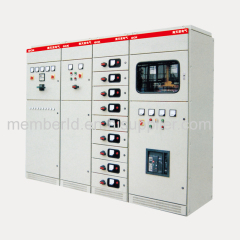
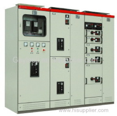
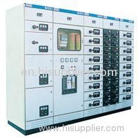
GCK Low-voltage Withdrawable Switchgear
Overview
The GCK series switchgear consists of a power distribution center (PC) cabinet and a motor control center (MCC) cabinet. Applicable to power users such as power plants, substations, industrial and mining enterprises, etc. as a power distribution system with 50 Hz AC, maximum working voltage to 660V, and maximum working current to 3150A, as power conversion for power distribution, motor control and lighting. For distribution control purposes. The product has high breaking capacity, good dynamic thermal stability, advanced and reasonable structure, practical and practical electrical scheme, strong series and versatility, and any combination of various scheme units. The cabinets contain more circuits and save land. The area, the appearance is beautiful, the protection level is high, the safety is reliable, and the maintenance is convenient.
Product Standards
The product complies with IEC60439 standard, and also meets the national standard GB7251-87 "Low-voltage switchgear" and ZBK36001-89 "Low-voltage withdrawable switchgear" standard.
Product model and its meaning
The main technical parameters
Structural features
The basic cabinets of GCK and GCL are assembled and assembled. All the structural parts of the cabinets are galvanized and spray-coated. They are connected to each other by screw fastening to form a basic cabinet frame. Then, as required, doors, baffles and partitions are added. The drawers, mounting brackets, and busbars and electrical components are assembled into a complete control center cabinet. The cabinet structure has the following features.
Cabinet
The frame is made of special-shaped steel, which is positioned by gussets and bolted with no welded structure.
a. The molding size of the parts, the opening size, and the device spacing are modularized. (modulus E = 20 m m, the same below).
b. Internal structural parts are galvanized.
c. External phosphating; then electrostatic epoxy powder coating.
d. The cabinet is divided into three separate sections: busbar, functional unit and cable, which can prevent accidents from spreading and facilitate electrification. The frame is made of profiled steel, with gusset positioning and bolted joints without welding.
a. The molding size of the parts, the opening size, and the device spacing are modularized. (modulus E = 20mm, the same below).
b. Internal structural parts are galvanized.
c. External phosphating; then electrostatic epoxy powder coating.
d. The cabinet is divided into three separate sections of busbar, functional unit and cable to prevent accident spread and easy to charge the functional unit (drawer part)
a. Functional unit: feed unit, motor unit, utility power unit.
b. The drawer module has a height modulus of 200mm and is divided into five series of sub-units, 1 unit, sub-unit, 2 unit and 3 units. The unit circuit is rated at 630A or below.
c. Each MCC cabinet can be installed with up to 9 one-unit drawers or 18 one-unit drawers.
d. The door panel of the compartment is mechanically interlocked with the drawer by the operating mechanism of the main switch. When the main switch is in the closing position, the door panel cannot be opened.
e. The operating mechanism of the main switch can be locked in the closing or opening position with a shackle, which can safely repair the electrical equipment.
f. The functional unit compartments are separated by a metal partition.
g. The shutter in the compartment is automatically opened and closed as the drawer is pushed and pulled out so that the vertical busbar is not accessible in the compartment.
Structural characteristics
1. The basic skeleton of the switchgear is a combined assembly structure. The whole structure of the cabinet frame is made by self-tapping screws, and the door, partition, sealing plate, bracket and busbar, drawer and electrical components are complete. Switch cabinet. Since the original GCKI skeleton adopts the GF28 profile, the profile steel plate is thinner, and in addition, when the profile is galvanized, a part of the interior has a dead angle, so that the service life of the cabinet is greatly shortened. At the same time, factors such as the standardization of its overall structure are taken into consideration. Our company boldly improved. Type C special profiles are used. It is made of 25mm modulus and 2mm thick steel plate. It is reinforced with self-tapping screws with strong rigidity during assembly, which makes the combination more flexible and convenient, and the service life is longer.
2. The switch cabinet adopts modular design and divides the cabinet into three zones. The top is the busbar area, the front is the electrical area, the rear is the cable outlet area, and the electrical and cable areas are separated by steel plates.
To ensure the normal operation of the line. Effectively prevent the fault from expanding. When the electrical components are pulled out of the cabinet, the charged body in the cabinet is not exposed. For the user, the use is safer and more reliable. For the feeder cabinet. The cabinet is 600mm wide. Up to 9 or 18 feed circuits can be installed. (18 feeder circuits are only suitable for load units with capacities below 63A)
3. According to the characteristics of the switchgear, it can be divided into power receiving cabinet, PC cabinet (power center), MCC cabinet (motor control center) and capacitor compensation cabinet.
4. The drawers of the same functional unit can be interchanged. Once the fault occurs, the unit is pulled out and the spare drawer is inserted, and the power can be sent. This greatly shortens the power failure time due to the fault and improves the reliability of the equipment.
5. The switch cabinet can be designed as a hybrid cabinet and a drawer cabinet. It can also be a drawer type that retains the simplicity, practicality and low cost of the fixed cabinet, and has the advantages of small volume, strong function and easy replacement.
6. In order to ensure the personal safety of the operating procedures and maintenance personnel, a mechanical interlocking mechanism is arranged in the switch cabinet, and a mechanical interlocking mechanism is arranged in the drawer unit and the door and the main switch. Make it use more
7. The height of the drawer of the switch cabinet is divided into four standard sizes, namely: 1 unit/2, 1 unit, 2 units, 3 units, which is light in structure, convenient in assembly, reasonable in layout, and has three positions of work, test and isolation.
8. The N and PE wires of the switchgear are at the lower rear of the switchgear, and the PE wire is connected with the cabinet frame, which not only makes the outlet cable connection more convenient. And the grounding is more reliable.
9. The ventilation system is provided at the top of the switchgear and the upper and lower ventilating doors without reducing the degree of protection.
■ shape and installation size
1. Dimensions
■Normal use of environmental conditions
The altitude should not exceed 2000m. The ambient air temperature is not higher than +409C, and the average temperature is not higher than +35 °C within 24h, and the ambient air temperature is not lower than -5 °C. Atmospheric conditions: air is clean, relative humidity does not exceed 50% at +40 °C, and higher relative humidity is allowed at lower temperatures. For example, 90% at +20 °C, no fire, explosion hazard, serious A place where pollution, chemical corrosion and severe vibrations occur. It is inclined no more than 5° from the vertical plane. The control center is adapted to the following temperature transport and storage processes, -25 ° C - +55 ° C, in a short time (not more than 24 h) does not exceed +70 ° C. If the above conditions of use cannot be met, the user shall submit it to our company at the time of ordering and resolve it by negotiation. The installation of the GCK series switchgear is not vertically installed on the wall, and the rear is the outlet cable trench of the cabinet. For maintenance, the rear wall is usually 1000-1200mm.


