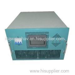
Battery Charger Rectifier Charging Sealed Rechargeable Battery Lithium Ion Battery Ni Cd Battery
Company Profile
| Location: | Beijing, China (Mainland) |
|---|---|
| Business Type: | Manufacturer |
| Main Products: | IGBT Rectifier, Rectifier, Dc Power Supply, Active Harmonic Filter, St |
Product Description
Battery charger application Self-regulated rectifier automatic battery charger, IGBT power supply converter, especially developed for powering critical loads associated to Sealed rechargeable battery, Lithium ion battery (Li-lon), Ni-Cd battery and Pb-acid battery bank, such as secure energy systems for substations, emergency lighting, communications etc. AC/DC converters and battery charger description
Green Power broad range of ac/dc converter and battery chargers, with power ratings from 3kwto 500kw, are suitable for almost any battery charging application where robust design and high reliability are required. The DC power supply has demonstrated to be a secure, reliable and economic way to provide reserve power supply for critical consumers. Used as a power supply of critical loads associated to a bank of batteries, of high reliability and great connectivity with data transmission networks for monitoring and parameter control. Features Robust design, High reliability
The reliability of the DC network will depend on the quality of the selected batteries, as well as the charger equipment that operates as charging system and maintenance. Custom design battery charging curve
Normalized load curve, work with a characteristic voltage-current output curve, the output current remains constant while the charger voltage does not surpass the established maximum. If this maximum voltage is surpassed, the charger behaves as a constant voltage supply, keeping the value of the output voltage constant for the protection of the equipment and the batteries connected to it. Automatic/Manual mode running
In the automatic mode, once primary energy has been reinstalled and with dead batteries, the rectifier is positioned in trickle charge delivering constant current to the batteries, until the established trickle voltage is reached, and from this moment on the rectifier switched to constant voltage. This situation is maintained during the time established by the equipment operator and defined from the control panel. That is, the trickle charge is timed.
In the manual mode, the transfer from float charge to trickle is made by the operator from the control panel. This trickle load will also be timed during the preestablished period by the user or he could end it by a resetting action. Modular design
Modular structure, parallel connection to expand output current. Compact size. Digital Control
Flexible and friendly programming, a microprocessor-based control composed by a master control and an interface unit with the user that acts as a control panel. All controls and displays on touch screen Output voltage and current displayCharger time displayAmpere hour displayRectifier status indicationAuto/Manual mode displayCC/CV modeCharging statusWhen the rectifier is charging battery, the red light is on. When it is not charging, the color is grey.Charged statusWhen the rectifier finishes charging, the red light is on. Otherwise, the color is grey.Alarm statusWhen there is no alarm, it shows red color continuously, when there is alarm, it is flashing.Cell numberIt shows number of series connected cells.Charging Status:Charging, charged, stop.
When there is fault with battery, it will show battery status, including:
When actual battery voltage exceeds set max. Voltage*cell number, it will show incorrect battery voltage.
When actual battery voltage is lower than set min. Voltage*cell number, it will show no battery.
The min. and max. voltage is set on touch panel.Technical Specifications Chargingrectifier outputCustom design, power 3kw-500kw3-Phase AC Input3 phase 230VAC, 380VAC, 415VAC, 440VAC, 480VAC, 550VAC, 600VAC, 50-60HzCharging ModeManualAutoOperator Panel Controls and IndicationsAC Isolator MCB : This MCB isolates the input power to the charger.Mains On Lamp : this lamp indicates the charger input power is on. Auto/Manualswitch: shift between AUTO and MANUAL modes of operation. In order to change the mode charger should be powered off , select the desired mode and then power the charger on again.Start Stop Switch : This push button switch is used to give start and stop charging command in MANUAL mode of operation. This switch is inactive in AUTO mode.Current Set: used to set the charging current in MANUAL mode of operation. Current set is inactive in AUTO mode.Output regulation range0-100% of max currentor voltageControl accuracy1/1000 of max current or voltageOperation ModeConstant current and constant voltage, constant powerRipple<3% on requestEfficiency>90% (typ.) @ rated load >92% (>= 100VDC) @rated loadDegree of ProtectionIP30 for air cooling IP44, IP54 for water cooling on requestPower factor>0.93 @ rated loadInsulation gradeBWorking mode100% 24 hours continuous runningAlarm typeAudible and visual alarmCooling methodAir cooling/water coolingAvailable Interfaces with PLCAnalogue 0-10V Analogue 4-20mA RS485(MODBUS) RS232 Profibus-DP ProfinetOperation ModesManual, AutomaticProtectionsShort circuit protection Over/under input voltage protection Driving protection Over heat protection Over current protection Over voltage protection

