

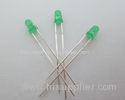
570 - 575nm light Indicator LED diffused green light emitting diode
| Place of Origin: | Zhejiang |
|---|
Company Profile
| Location: | Shenzhen, Guangdong, China (Mainland) |
|---|---|
| Business Type: | Manufacturer |
Product Detail
| Model No.: | DL-304YGDA-1YG60 |
|---|
Product Description
570 - 575nm light Indicator LED diffused green light emitting diode
- Features:
- Popular T-1 diameter package.
- High efficiency.
- Selected minimum intensities.
- Available on tape and reel.
- Reliable and robust.
- The product itself will remain within RoHS compliant Version.
- Descriptions:
- The series is specially designed for applications requiring higher brightness.
- The LED lamps are available with different colors, intensities.
- Applications:
- Status indicators.
- Commercial use.
- Advertising Signs.
- Back lighting.
| Part No. | Chip Material | Lens Color | Source Color |
| DL-304YGDA-1YG60 | GaAlAs | YG | Yellow Green |
- Package Dimension:

Notes:
- All dimensions are in millimeters (inches).
- Tolerance is ± 0.25mm (.010″) unless otherwise noted.
- Protruded resin under flange is 1.00mm (.039″) max.
- Specifications are subject to change without notice.
- Absolute Maximum Ratings at Ta=25
-
Parameters Symbol Max. Unit Power Dissipation PD 60 mW Peak Forward Current
(1/10 Duty Cycle, 0.1ms Pulse Width)
IFP 100 mA Forward Current IF 25 mA Reverse Voltage VR 5 V Operating Temperature Range Topr -40 to +85 Storage Temperature Range Tstg -40 to +100 Lead Soldering Temperature
[4mm (.157″) From Body]
Tsld 260 for 5 Seconds Electrical Optical Characteristics at Ta=25
Parameters Symbol Min. Typ. Max. Unit Test Condition Luminous Intensity * IV 30 50 --- mcd IF=20mA (Note 1) Viewing Angle * 2θ1/2 --- 60 --- Deg IF=20mA (Note 2) Peak Emission Wavelength λp --- 570 --- nm IF=20mA Dominant Wavelength λd --- 572 --- nm IF=20mA (Note 3) Spectral Line Half-Width λ --- 25 --- nm IF=20mA Forward Voltage VF 1.80 2.20 2.80 V IF=20mA Reverse Current IR --- --- 10 µA VR=5V Notes:
- Luminous Intensity Measurement allowance is ± 10%.
- θ1/2 is the off-axis angle at which the luminous intensity is half the axial luminous intensity.
- The dominant wavelength (λd) is derived from the CIE chromaticity diagram and represents the single wavelength which defines the color of the device.
-
- Typical Electrical / Optical Characteristics Curves
-
(25 Ambient Temperature Unless Otherwise Noted)

Confidence level: 90%. LTPD: 10%.
1) Test Items and Results:
Test Item Standard Test Method Test Conditions Note Number of Damaged Resistance to Soldering Heat JEITA ED-4701
300 302
Tsld=260±5, 10sec 3mm from the base of the epoxy bulb 1 time 0/100 Solder ability JEITA ED-4701
300 303
Tsld=235±5, 5sec(using flux) 1time
over 95%
0/100 Thermal Shock JEITA ED-4701
300 307
0~100 15sec, 15sec 100 cycles 0/100 Temperature Cycle JEITA ED-4701
100 105
-40~25~100~25 30min,5min,30min,5min 100 cycles 0/100 Moisture Resistance Cycle JEITA ED-4701
200 203
25~65~-10 90%RH 24hrs/1cycle 10 cycles 0/100 High Temperature Storage JEITA ED-4701
200 201
Ta=100 1000hrs 0/100 Terminal Strength
(Pull test)
JEITA ED-4701
400 401
Load 10N (1kgf)
10±1sec
No noticeable damage Post Buying Request