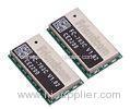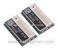

GFSK Wireless m bus module with UART interface for serial communication and configuration
| Place of Origin: | Zhejiang |
|---|
Company Profile
| Location: | Shenzhen, Guangdong, China (Mainland) |
|---|---|
| Business Type: | Manufacturer |
Product Detail
| Model No.: | FC-703C |
|---|
Product Description
868MHZ Wireless M-Bus module FC-703C with UART Interface
1. Technical Specification
| Item | Min | Typ. | Max | Unit |
| Frequency bands | 868 | 870 | MHz | |
| Number of channels | 12 | |||
| Supply voltage VCC | 2.2 | 3.3 | 3.6 | VDC |
| Voltage on any pin | VCC-0.7 | VCC | VDC | |
| TX Current (RF_POWER=5/10dbm) | 40 | mA | ||
| RX Current | 24 | mA | ||
| Sleep Current | 0.6 | uA | ||
| Input/output impedance | 50 | Ohm | ||
| RF Data rate | 4.8 32.768 100 | kchip/s | ||
| Max RF output power(VCC=3.3V) | 10 | dBm | ||
| Sensitivity, 32.768K | -102 | dBm | ||
| Spurious emission, TX < 1 GHz > 1 GHz | -36 -30 | dBm | ||
| Sensitivity(32.768K) | -102 | dBm | ||
| Blocking 1 MHz 4 MHz 8 MHz | –52 –56 –63 | dBm | ||
| Image Rejection | –30 | dBm | ||
| Spurious Emissions | -54 | dBm | ||
| Harmonics | –42 | dBm | ||
| Minimum RST Low Time to Generate a System Reset | 15 | μs | ||
| Operating temperature | -40 | 80 | °C | |
| Storage temperature | -50 | 150 | °C | |
| Weight | 5 | g |
2. Brief Description
FC-703C RF transceiver module follows the wireless M-BUS protocol. It has a UART interface for serial communication and configuration. The dimension is 13.7*25.4*3.4mm.FC-703C can work in S, T, R2 and C mode. It works in sleeping mode with super-low consumption power and be wakened up via serial port. By mounting the module onto the user board, it is easy to use through serial port communication protocol.


3.Main Applications
AMR/AMI
Electricity meters
Gas and Water meters
Heat meters, Heat cost allocators
Handheld device and gateways
In-Home Display and wireless sensor
4.Pin Assignment and Description
| Pin | Name | Describe |
| 1 | GND | Ground |
| 2-7 | RESERVED | For test and future extension, not connected |
| 8 | RTS | Receive flow control I, output, high: idle, low: busy. |
| 9 | CTS | Send flow control O, input high: idle , low: busy |
| 10 | RESERVED | For test and future extension, not connected |
| 11 | CONFIG | Reserved |
| 12 | GND | Ground |
| 13 | GND | Ground |
| 14 | VCC | POWER SUPPLY |
| 15 | GND | Ground |
| 16 | GND | Ground |
| 17 | RF | RF pin, connect with antenna |
| 18 | GND | Ground |
| 19 | GND | Ground |
| 20-24 | RESERVED | For test and future extension, not connected |
| 25 | LED1 | LED1 output. If not needed, not connected. Active high. |
| 26 | LED2 | LED2 output. If not needed, not connected. Active high. |
| 27 | RXD | Serial RX |
| 28 | TXD | Serial TX |
| 29 | RESET | Reset Pin (active in low) |
| 30 | GND | Ground |
5.Typical Application Description


