customized high-precision current transformer
| Min. Order: | 10 Piece/Pieces |
|---|---|
| Trade Term: | FOB,CFR,CIF,FAS,CIP,CPT,FCA,EXW |
| Payment Terms: | Paypal, L/C, D/P, D/A, T/T, WU, Money Gram |
| Place of Origin: | Zhejiang |
Company Profile
| Location: | Jiaxing, Zhejiang, China (Mainland) |
|---|---|
| Business Type: | Manufacturer |
| Main Products: | Current Transformer, Transformer, Common Mode Inductor, Magnetic Core |
Product Detail
| Means of Transport: | Ocean, Air |
|---|---|
| customization: | RoHs compliant |
| Packing: | can be customized |
Product Description
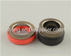
CTS series are high-precision current transformers, they are manufactured strictly under the instruction of "a current transformer" patent technology of patent number CN102709042B. Their measurement accuracy can be:0.02S,0.01S,0.005,and are mainly used for the AC measurement of instruments and meters.
CTS series
amplitude error(ratio error)±(%)
amplitude error(ratio error)±(%) | ||||||||||
accuracy class | Imax | 0.5 Imax | 2In | In | 0.5In | 0.2In | 0.1In | 0.05 In | 0.02 In | 0.01In |
0.02 | 0.02 | 0.02 | 0.02 | 0.02 | 0.02 | 0.02 | 0.02 | 0.02 | 0.02 | 0.04 |
0.01 | 0.01 | 0.01 | 0.01 | 0.01 | 0.01 | 0.01 | 0.01 | 0.01 | 0.01 | 0.02 |
0.005 | 0.005 | 0.005 | 0.005 | 0.005 | 0.005 | 0.005 | 0.005 | 0.005 | 0.005 | 0.01 |
phase error(angle error)(′)
phase error(angle error)(′) | ||||||||||
accuracy class | Imax | 0.5Imax | 2In | In | 0.5In | 0.2In | 0.1In | 0.05In | 0.02In | 0.01In |
0.02 | 0.6 | 0.6 | 0.6 | 0.6 | 0.6 | 0.6 | 0.6 | 0.6 | 0.6 | 1.2 |
0.01 | 0.3 | 0.3 | 0.3 | 0.3 | 0.3 | 0.3 | 0.3 | 0.3 | 0.3 | 0.6 |
0.005 | 0.15 | 0.15 | 0.15 | 0.15 | 0.15 | 0.15 | 0.15 | 0.15 | 0.15 | 0.3 |
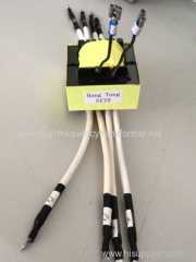
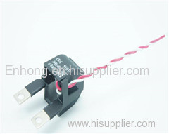
Instructions:CTS series current transformer are the current transformer of voltage output,red wire is the anode of current transformer output voltage, which is connected to the anode of current signal input of metering chip (+In),white wire is the cathode of current transformer output voltage, which is connected to the cathode of current signal input of metering chip (-In). Putting bias resistors R0 between the cathode (-In) of current signal input of the metering chip and the ground wire, the value range of bias resistors can be between 0Ω~10kΩ. Resistance value of bias resistors advised to choose 10Ω; connecting current sampling resistance R1,R2 to the interior of current transformer,current sampling resistance R1 and crrent sampling resistance R2 are substitutional resistor of 10 Ω .
Model | Rated Pr.Curren In(A) | Max.Curren Imax(A) | Rated Output Voltage of secondary side(mV) | accuracy class (class) |
CTS1.5(10)A/50mV0.01S | 1.5 | 10 | 50 | 0.01 |
CTS1.5(10)A/50mV0.005S | 1.5 | 10 | 50 | 0.005 |
CTS1.5(10)A/50mV0.002S | 1.5 | 10 | 50 | 0.002 |
CTS0.3(1.2)A/10mV0.01S | 0.3 | 1.2 | 10 | 0.01 |
CTS0.3(1.2)A/10mV0.005S | 0.3 | 1.2 | 10 | 0.005 |
CTS0.3(1.2)A/10mV0.002S | 0.3 | 1.2 | 10 | 0.002 |
CTS0.3(6)A/10mV0.01S | 0.3 | 6 | 10 | 0.01 |
CTS0.3(6)A/10mV0.005S | 0.3 | 6 | 10 | 0.005 |
CTS0.3(6)A/10mV0.002S | 0.3 | 6 | 10 | 0.002 |
Reference circuit parameters configuration:
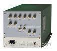
example: energy metering module
design specification:three-phase four-wire system,voltage specification is:3 X 220V/380V, current specification is:3 X 1.5(6)A.
Metering chip:ATT7022EU
Current sampling:Current transformer is CTSU1.5(6)A/50mV0.01S,Bias resistors R0 is 10Ω,when under rated current transformer, the signal voltage of the current circuit is 0.05V
Voltage sampling:Using resistance to share partial pressure, the signal voltage of the voltage loop is 0.2V.
Metering chip ATT7022E parameter configuration: the gain configuration of the current channel is 1, the gain configuration of the voltage channel is 1.
Measurement error precision test:
Test data of active measurement error:In=1.5A,
Precision grade of calibration machine: 0.03
The environmental temperature:23℃
electric current | Active measurement error | |
1.0L | 0.5L | |
4 In | 0.0111 | -0.0044 |
2 In | 0.0066 | 0.0133 |
In | -0.0066 | 0.0111 |
0.5 In | 0.0053 | 0.0284 |
0.2 In | 0.0097 | 0.0293 |
0.1 In | 0.0071 | 0.0259 |
0.05 In | 0.0094 | 0.0394 |
0.01 In | -0.0140 | 0.0001 |
4. Electrical properties
4.1 Dielectric strength:power frequency voltage between the primary winding and the secondary winding is 4KV/min,no breakdown,flashover phenomenon,leakage current<1mA;
4.2 Insulation resistance:between the primary winding and the secondary winding≥ 1000MΩ/500Vdc;
4.3 The temperature rise limit:According to the temperature influence regulations of GB/T17215, when the environment temperature is 40 ℃, under the Imax current, the temperature rise of the electric transformer shell surface must be less than 25 k.
4.4 Overload capacity test:Under the rated load, after 30 Imax current impacts the current transformer for half a period, the current transformer is still in good condition, when back to the rated current, the error of the current transformer is no more than 1.3 times of the regulated value. After demagnetization, the current transformer still satisfies the requirement of level of accuracy.
5. The working environment
The limiting ambient temperature:—40℃~+85℃;Relative humidity:≤98(25℃);
The altitude:≤3000m