bushing removal tool kit
| Min. Order: | 100 Set/Sets |
|---|---|
| Trade Term: | FOB |
| Payment Terms: | Paypal, L/C, T/T |
| Supply Ability: | 5000 Sets Per Month |
| Place of Origin: | Zhejiang |
Company Profile
| Location: | Hangzhou, Zhejiang, China (Mainland) |
|---|---|
| Business Type: | Manufacturer, Distributor/Wholesaler, Service |
Product Detail
| Model No.: | LT6250 |
|---|---|
| Means of Transport: | Ocean, Air, Land |
| Model No:: | LT6250 |
| Place of Origin: | Zhejiang China(Mainland) |
| Packing: | Blow Box |
| Color: | Red/Blue/Black |
| Port: | Ningbo/Shanghai |
| Pricing Term: | FOB |
| Delivery Time: | 30 Days |
| Payment Term: | L/C,T/T,Paypal |
| Transport: | Sea,Air,Land |
| Means of Transport: | Ocean,Land,Air |
| Production Capacity: | 5000 Sets Per Month |
| Packing: | Blow Box |
| Delivery Date: | 30 Days |
Product Description
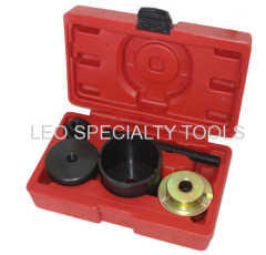
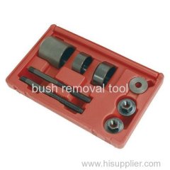
opel&vauxhall bushing removal tool

Description:
Intended for rapid removal/installation of Vauxhall/Opel Vectra (95-02) upper and lower rear trailing arm bushes.
Bushes are quickly pressed in or out with tool and a 19mm ratchet wrench (not included).

Applications:
Vauxhall/Opel; Vectra (95-02)
Operation:
3.1. REMOVING A BUSH. (Refer to Figs 2 & 3)
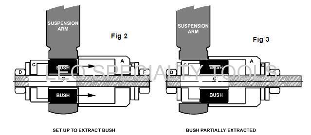
3.1.1. Screw the nut with washer attached (D) onto the short threaded portion of threaded rod (G). Slide the pushing cup (C) onto
the threaded rod in the orientation shown above in fig.2.
3.1.2. Push the threaded rod through the centre of the bush to be removed until the pushing cup bears against the bush.
3.1.3. Hold the assembly in place and slide the large static cup (A) onto the rod until it bears against the surface of the suspension
arm as shown above in fig.2.
3.1.4. Slide washer (E) onto the rod and retain the whole assembly by screwing the nut with washer (F) onto the threaded rod.
3.1.5. Hold nut D with a spanner and then place a second spanner over the nut with washer attached (F).
3.1.6. Disassemble the extractor and dispose of the old bush.
3.2. INSERTING A BUSH. (Refer to Figs 4 & 5)

3.2.1. Screw the nut with washer attached (D) onto the short threaded portion of threaded rod (G). Slide the small static cup (B)
onto the threaded rod in the orientation shown above in fig.4.
3.2.2. Hold the assembly against the suspension arm so that the static cup (B) is aligned with the hole in the arm with the threaded rod
sticking through to the other side.
3.2.3. Slide the new bush onto the threaded rod and align it with the hole in the arm. Place the pushing cup (C) up against the bush
and slide on the washer (E). Retain the whole assembly by screwing on the nut with washer (F). Before commencing insertion
ensure that the assembly is aligned with the hole in the suspension arm as shown in fig.4.
3.2.4. Hold nut D with a spanner and then place a second spanner over the nut with washer attached (F). This should preferably be a
ratchet ring spanner for ease of use and maximum accessability. As the nut is turned insertion will commence as indicated in
fig.5. Take care not to drive the bush too far into the suspension arm. Cease insertion when the bush is fully inserted into the
arm as shown in fig.5.
Packing details:
QTY(SET) | G.W.(KGS) | N.W.(KGS) | MEAS(CM) |
5 | 12 | 11 | 46*27*17 |