
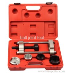

ball joint removal kit
| Min. Order: | 100 Set/Sets |
|---|---|
| Trade Term: | FOB |
| Payment Terms: | Paypal, L/C, T/T |
| Supply Ability: | 5000 Sets Per Month |
| Place of Origin: | Zhejiang |
Company Profile
| Location: | Hangzhou, Zhejiang, China (Mainland) |
|---|---|
| Business Type: | Manufacturer, Distributor/Wholesaler, Service |
Product Detail
| Model No.: | LT6256 |
|---|---|
| Means of Transport: | Ocean, Air, Land |
| Model No:: | LT6256 |
| Place of Origin: | Zhejiang China(Mainland) |
| Packing: | Blow Box |
| Color: | Red/Blue/Black |
| Port: | Ningbo/Shanghai |
| Pricing Term: | FOB |
| Delivery Time: | 30 Days |
| Payment Term: | L/C,T/T,Paypal |
| Transport: | Sea,Air,Land |
| Means of Transport: | Ocean,Land,Air |
| Production Capacity: | 5000 Sets Per Month |
| Packing: | Blow Box |
| Delivery Date: | 30 Days |
Product Description
bmw ball joint tool

Description:
This tool is designed to remove and install press-fit control arm ball joints on BMW 3 series cars (E36).Simple, easy hydraulic ram action.
Ball joints can be quickly removed and installed in-situ, by selecting and arranging the adaptors within the frame in the specific order required for removal or installation, as detailed below. Force is applied with the force screw.
The adaptors are identified 5,6,7 and 8 as shown in fig.1.
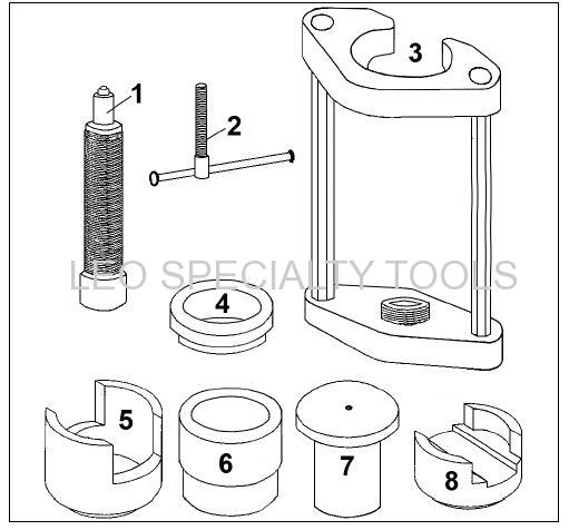
ITEM | DESCRIPTION |
1 | FORCE SCREW |
2 | T=HANDLE |
3 | MAIN FRAME |
4 | ADAPTOR RING |
5 | ADAPTOR - A |
6 | ADAPTOR - B |
7 | ADAPTOR - C |
8 | ADAPTOR - D |
Instructions:
1.PREPARATION REQUIRED TO REMOVE BALL JOINT.
1.1. Unscrew nut on stabiliser connection on the control arm.
1.2. Unscrew nut on the ball joint until it touches the spring strut and separate the ball joint from axle using a suitable tapered separator fork.
1.3. Unscrew and remove the ball joint nut.
1.4. Push the axle journal outward to give access to the ball joint/control arm, and support steering knuckle in position.

2. REMOVING BALL JOINT. (See fig.1. for adaptor assembly sequence).
2.1. Fit adaptor 7 over the ball joint gaiter and locate it in the rubber bonded joint recess.
2.2. Position the open end of adaptor 5 over the lower part of the ball joint to rest on underside of the control arm face.
2.3. Ensure the force screw is well lubricated and unscrew to give maximum opening within the frame.
2.4. Holding the adaptors in place, position the frame over the ball joint and adaptor assembly, locating the recess in adaptor 7 in the top of the frame.
2.5. Screw in force screw so that the bearing assembly aligns with the recess in adaptor 5.
2.6. Continue to screw in the force screw assembly to extract the ball joint out of the control arm.
2.7. Remove any rust from the lower face of the control arm using a wire brush and clean the bore.
DO NOT APPLY GREASE. Control arm bore and ball joint must be clean and free from grease.
3. INSTALLING NEW BALL JOINT. (See fig.1. for adaptor assembly sequence).
3.1. Fit adaptor 6 over control arm (fig.1.).
3.2. Insert adaptor and ball joint assembly into underside of control arm bore.
IMPORTANT: It is essential to ensure the ball joint is correctly and accurately aligned with the installation position marked on the control arm prior to removal of old ball joint (fig.2). Place open end of adaptor 8 on the bottom of the ball joint and position the frame in alignment with the joint.

3.3. Lubricate the force screw well and screw it in until the bearing locates in the recess in the bottom of adaptor 8.
3.4. Continue to turn the force screw to press the ball joint FULLY HOME into the control arm.
4. RE-ASSEMBLY.
4.1. Screw a new self locking nut on ball joint.
4.2. To assist when tightening the nut, hold up the ball joint/control arm with a jack.
4.3. Replace self locking nut and fit washer on stabiliser connection on the control arm.
4.4. Tighten all nuts to specified torque.
Packing details:
QTY(SET) | G.W.(KGS) | N.W.(KGS) | MEAS(CM) |
2 | 12 | 11 | 39*17*26 |