power thermistor power thermistor
| Min. Order: | 500 Piece/Pieces |
|---|---|
| Trade Term: | FOB,CFR,CIF,EXW |
| Payment Terms: | L/C, T/T |
| Supply Ability: | 5000k pieces a month |
| Place of Origin: | Guangdong |
Company Profile
| Location: | Dongguan, Guangdong, China (Mainland) |
|---|---|
| Business Type: | Manufacturer |
| Main Products: | Ceramic Capacitor, Film Capacitor, NTC Thermistor, High Voltage Ceramic Capacitor (4KV-6KV-8KV-10KV-12KV-15KV), High Voltage Ceramic Capacitor (1KV-2KV-3KV) |
Product Detail
| Model No.: | NTC |
|---|---|
| Means of Transport: | Ocean, Land |
| Package Type: | Throught Hole |
| Type: | Thermal Resistor |
| Brand Name: | zhengli |
| MPQ: | 500pieces |
| Production Capacity: | 5000k pieces a month |
| Packing: | 500 pieces a bag |
| Delivery Date: | 4 weeks |
Product Description
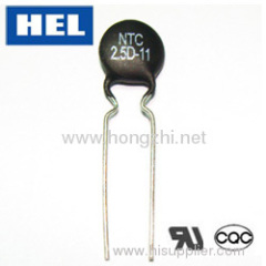
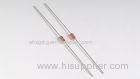
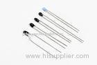
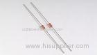
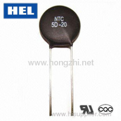
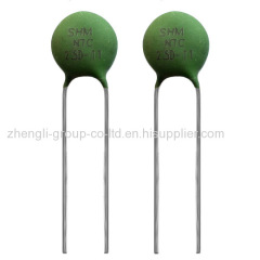
NTC thermistor
1.Power NTC thermistor introduction
Power NTC thermistor has en excellent non-linearity characteristic for the resistance and temperature ,its appliance is an easy and effective method to protect electronic device through surge current restraining .
2.Resistance and temperature characteristic of power NTC thermistor
Power NTC thermistor can effectively restrain the surge current in the circuit ,and its resistance will fall down to a very small state through the current durative and the power consumption is commonly ignored , the coltage will be borne by the rear divice so that to guarantee the normal function of circuit .
The intergradations metal oxide as the main material , power NTC thermistor is a kind of semi-conductive component manufactured by the ceramic productive process technique ,it belongs to the category of negative thermistor series .
3.Range of application
Power NTC thermistor are widely applied in switch power ,conversion power supply ,UPS power and electronic rectifier ,heater ,etc , it has a protected function for RT ,display ,lighting device and circuit of different electronic equipments .
4.Nomenclature explanation
1. Zero-power resistance (R25) : the measured resistance of power NTC thermistor under the condition of 25C with a rated zero-power .
2. The maximum steady current (Imax):the maximum current that could be allowed connecting with the power NTC thermistor under the rated current condition (virtual value)
5.Characteristic of power NTC thermistor
1. Power NTC thermistors are in small size but with a high power that to restrain the surge current .
2. Powe NTC thermistors possesse the electronic character of fast reflection ,high reliability and long-life time for use.
3. The material has a high constant as B value with small remained resistance .
4. Power NTC thermistors have a large application range integrate products series .
6.Recognized standards and certificates
Recognized organization | Recognized marks | Recognized standard | Certificates series No |
UL | E361907 | ||
CUL | E361907 |
10.Main parameter and dimensions of △D-5 and △D-7
type | Rated zero-power resistance R25(Ω) | Maximum steady state current Imax(A) | dimensions(mm) | |||||||
D±1 | F1±1 | F2±1.5 | T±0.5 | d±0.05 | Straight lead | Kink lead | ||||
L1 | L1 / | L2±2 | ||||||||
5D-5 | 5 | 1 | 5.5 | 5.0/2.5 | 3 | 3.5 | 0.55/0.45 | 25 | 25/5 | 6 |
10D-5 | 10 | 0.7 | 5.5 | 5.0/2.5 | 3 | 3.5 | 0.55/0.45 | 25 | 25/5 | 6 |
15D-5 | 15 | 0.6 | 5.5 | 5.0/2.5 | 3 | 3.5 | 0.55/0.45 | 25 | 25/5 | 6 |
20D-5 | 20 | 0.6 | 5.5 | 5.0/2.5 | 3 | 3.5 | 0.55/0.45 | 25 | 25/5 | 6 |
22D-5 | 22 | 0.6 | 5.5 | 5.0/2.5 | 3 | 3.5 | 0.55/0.45 | 25 | 25/5 | 6 |
33D-5 | 33 | 0.5 | 5.5 | 5.0/2.5 | 3 | 3.5 | 0.55/0.45 | 25 | 25/5 | 6 |
47D-5 | 47 | 0.4 | 5.5 | 5.0/2.5 | 3 | 3.5 | 0.55/0.45 | 25 | 25/5 | 6 |
68D-5 | 68 | 0.4 | 5.5 | 5.0/2.5 | 3 | 3.5 | 0.55/0.45 | 25 | 25/5 | 6 |
200D-5 | 200 | 0.1 | 5.5 | 5.0/2.5 | 3 | 3.5 | 0.55/0.45 | 25 | 25/5 | 6 |
5D-7 | 5 | 2 | 7.5 | 5 | 3 | 4 | 0.55 | 25 | 25/5 | 6 |
8D-7 | 8 | 1 | 7.5 | 5 | 3 | 4 | 0.55 | 25 | 25/5 | 6 |
10D-7 | 10 | 1 | 7.5 | 5 | 3 | 4 | 0.55 | 25 | 25/5 | 6 |
12D-7 | 12 | 1 | 7.5 | 5 | 3 | 4 | 0.55 | 25 | 25/5 | 6 |
16D-7 | 16 | 0.7 | 7.5 | 5 | 3 | 4 | 0.55 | 25 | 25/5 | 6 |
20D-7 | 20 | 0.6 | 7.5 | 5 | 3 | 4 | 0.55 | 25 | 25/5 | 6 |
22D-7 | 22 | 0.6 | 7.5 | 5 | 3 | 4 | 0.55 | 25 | 25/5 | 6 |
33D-7 | 33 | 0.5 | 7.5 | 5 | 3 | 4 | 0.55 | 25 | 25/5 | 6 |
11.Main parameter and dimensions of △D-9
type | Rated zero-power resistance R25(Ω) | Maximum steady state current Imax(A) | dimensions(mm) | |||||||
D±1 | F1±1 | F2±1.5 | T±0.5 | d±0.05 | Straight lead | Kink lead | ||||
L1 | L1 / | L2±2 | ||||||||
3D-9 | 3 | 4 | 9.5 | 7.5/5.0 | 5/3 | 4.5 | 0.75/0.55 | 25 | 25/5 | 6 |
4D-9 | 4 | 3 | 9.5 | 7.5/5.0 | 5/3 | 4.5 | 0.75/0.55 | 25 | 25/5 | 6 |
5D-9 | 5 | 3 | 9.5 | 7.5/5.0 | 5/3 | 4.5 | 0.75/0.55 | 25 | 25/5 | 6 |
6D-9 | 6 | 2 | 9.5 | 7.5/5.0 | 5/3 | 4.5 | 0.75/0.55 | 25 | 25/5 | 6 |
8D-9 | 8 | 2 | 9.5 | 7.5/5.0 | 5/3 | 4.5 | 0.75/0.55 | 25 | 25/5 | 6 |
10D-9 | 10 | 2 | 9.5 | 7.5/5.0 | 5/3 | 4.5 | 0.75/0.55 | 25 | 25/5 | 6 |
12D-9 | 12 | 1 | 9.5 | 7.5/5.0 | 5/3 | 4.5 | 0.75/0.55 | 25 | 25/5 | 6 |
16D-9 | 16 | 1 | 9.5 | 7.5/5.0 | 5/3 | 4.5 | 0.75/0.55 | 25 | 25/5 | 6 |
20D-9 | 20 | 1 | 9.5 | 7.5/5.0 | 5/3 | 4.5 | 0.75/0.55 | 25 | 25/5 | 6 |
22D-9 | 22 | 1 | 9.5 | 7.5/5.0 | 5/3 | 4.5 | 0.75/0.55 | 25 | 25/5 | 6 |
30D-9 | 30 | 1 | 9.5 | 7.5/5.0 | 5/3 | 4.5 | 0.75/0.55 | 25 | 25/5 | 6 |
33D-9 | 33 | 1 | 9.5 | 7.5/5.0 | 5/3 | 4.5 | 0.75/0.55 | 25 | 25/5 | 6 |
50D-9 | 50 | 1 | 9.5 | 7.5/5.0 | 5/3 | 4.5 | 0.75/0.55 | 25 | 25/5 | 6 |
60D-9 | 60 | 0.8 | 9.5 | 7.5/5.0 | 5/3 | 4.5 | 0.75/0.55 | 25 | 25/5 | 6 |
80D-9 | 80 | 0.8 | 9.5 | 7.5/5.0 | 5/3 | 4.5 | 0.75/0.55 | 25 | 25/5 | 6 |
120D-9 | 120 | 0.8 | 9.5 | 7.5/5.0 | 5/3 | 4.5 | 0.75/0.55 | 25 | 25/5 | 6 |
200D-9 | 200 | 0.5 | 9.5 | 7.5/5.0 | 5/3 | 4.5 | 0.75/0.55 | 25 | 25/5 | 6 |
400D-9 | 400 | 0.2 | 9.5 | 7.5/5.0 | 5/3 | 4.5 | 0.75/0.55 | 25 | 25/5 | 6 |
12.Main parameter and dimensions of △D-11
type | Rated zero-power resistance R25(Ω) | Maximum steady state current Imax(A) | dimensions(mm) | |||||||
D±1 | F1±1 | F2±1.5 | T±0.5 | d±0.05 | Straight lead | Kink lead | ||||
L1 | L1 / | L2±2 | ||||||||
2.5D-11 | 2.5 | 5 | 11.5 | 7.5/5.0 | 5/3 | 4.5 | 0.75 | 25 | 25/5 | 6 |
3D-11 | 3 | 5 | 11.5 | 7.5/5.0 | 5/3 | 4.5 | 0.75 | 25 | 25/5 | 6 |
4D-11 | 4 | 4 | 11.5 | 7.5/5.0 | 5/3 | 4.5 | 0.75 | 25 | 25/5 | 6 |
5D-11 | 5 | 4 | 11.5 | 7.5/5.0 | 5/3 | 4.5 | 0.75 | 25 | 25/5 | 6 |
6D-11 | 6 | 3 | 11.5 | 7.5/5.0 | 5/3 | 4.5 | 0.75 | 25 | 25/5 | 6 |
8D-11 | 8 | 3 | 11.5 | 7.5/5.0 | 5/3 | 4.5 | 0.75 | 25 | 25/5 | 6 |
10D-11 | 10 | 3 | 11.5 | 7.5/5.0 | 5/3 | 4.5 | 0.75 | 25 | 25/5 | 6 |
12D-11 | 12 | 2 | 11.5 | 7.5/5.0 | 5/3 | 4.5 | 0.75 | 25 | 25/5 | 6 |
16D-11 | 16 | 2 | 11.5 | 7.5/5.0 | 5/3 | 4.5 | 0.75 | 25 | 25/5 | 6 |
20D-11 | 20 | 2 | 11.5 | 7.5/5.0 | 5/3 | 4.5 | 0.75 | 25 | 25/5 | 6 |
22D-11 | 22 | 2 | 11.5 | 7.5/5.0 | 5/3 | 4.5 | 0.75 | 25 | 25/5 | 6 |
30D-11 | 30 | 1.5 | 11.5 | 7.5/5.0 | 5/3 | 4.5 | 0.75 | 25 | 25/5 | 6 |
33D-11 | 33 | 1.5 | 11.5 | 7.5/5.0 | 5/3 | 4.5 | 0.75 | 25 | 25/5 | 6 |
50D-11 | 50 | 1.5 | 11.5 | 7.5/5.0 | 5/3 | 4.5 | 0.75 | 25 | 25/5 | 6 |
60D-11 | 60 | 1.5 | 11.5 | 7.5/5.0 | 5/3 | 4.5 | 0.75 | 25 | 25/5 | 6 |
80D-11 | 80 | 1.2 | 11.5 | 7.5/5.0 | 5/3 | 4.5 | 0.75 | 25 | 25/5 | 6 |
13.Main parameter and dimensions of △D-13
type | Rated zero-power resistance R25(Ω) | Maximum steady state current Imax(A) | dimensions(mm) | |||||||
D±1 | F1±1 | F2±1.5 | T±0.5 | d±0.05 | Straight lead | Kink lead | ||||
L1 | L1 / | L2±2 | ||||||||
1.3D-13 | 1.3 | 7 | 13.5 | 7.5 | 5 | 5.5 | 0.75 | 25 | 25/5 | 6 |
1.5D-13 | 1.5 | 7 | 13.5 | 7.5 | 5 | 5.5 | 0.75 | 25 | 25/5 | 6 |
2.5D-13 | 2.5 | 6 | 13.5 | 7.5 | 5 | 5.5 | 0.75 | 25 | 25/5 | 6 |
3D-13 | 3 | 6 | 13.5 | 7.5 | 5 | 5.5 | 0.75 | 25 | 25/5 | 6 |
4D-13 | 4 | 5 | 13.5 | 7.5 | 5 | 5.5 | 0.75 | 25 | 25/5 | 6 |
5D-13 | 5 | 5 | 13.5 | 7.5 | 5 | 5.5 | 0.75 | 25 | 25/5 | 6 |
6D-13 | 6 | 4 | 13.5 | 7.5 | 5 | 5.5 | 0.75 | 25 | 25/5 | 6 |
7D-13 | 7 | 4 | 13.5 | 7.5 | 5 | 5.5 | 0.75 | 25 | 25/5 | 6 |
8D-13 | 8 | 4 | 13.5 | 7.5 | 5 | 5.5 | 0.75 | 25 | 25/5 | 6 |
10D-13 | 10 | 4 | 13.5 | 7.5 | 5 | 5.5 | 0.75 | 25 | 25/5 | 6 |
12D-13 | 12 | 3 | 13.5 | 7.5 | 5 | 5.5 | 0.75 | 25 | 25/5 | 6 |
15D-13 | 15 | 3 | 13.5 | 7.5 | 5 | 5.5 | 0.75 | 25 | 25/5 | 6 |
16D-13 | 16 | 3 | 13.5 | 7.5 | 5 | 5.5 | 0.75 | 25 | 25/5 | 6 |
20D-13 | 20 | 3 | 13.5 | 7.5 | 5 | 5.5 | 0.75 | 25 | 25/5 | 6 |
30D-13 | 30 | 2.5 | 13.5 | 7.5 | 5 | 5.5 | 0.75 | 25 | 25/5 | 6 |
47D-13 | 47 | 2 | 13.5 | 7.5 | 5 | 5.5 | 0.75 | 25 | 25/5 | 6 |
120D-13 | 120 | 1.5 | 13.5 | 7.5 | 5 | 5.5 | 0.75 | 25 | 25/5 | 6 |
14.Main parameter and dimensions of △D-15
type | Rated zero-power resistance R25(Ω) | Maximum steady state current Imax(A) | dimensions(mm) | |||||||
D±1 | F1±1 | F2±1.5 | T±0.5 | d±0.05 | Straight lead | Kink lead | ||||
L1 | L1 / | L2±2 | ||||||||
1.3D-15 | 1.3 | 8 | 15.5 | 7.5 | 5 | 6 | 0.75 | 25 | 25/5 | 6 |
1.5D-15 | 1.5 | 8 | 15.5 | 7.5 | 5 | 6 | 0.75 | 25 | 25/5 | 6 |
3D-15 | 3 | 7 | 15.5 | 7.5 | 5 | 6 | 0.75 | 25 | 25/5 | 6 |
5D-15 | 5 | 6 | 15.5 | 7.5 | 5 | 6 | 0.75 | 25 | 25/5 | 6 |
6D-15 | 6 | 5 | 15.5 | 7.5 | 5 | 6 | 0.75 | 25 | 25/5 | 6 |
7D-15 | 7 | 5 | 15.5 | 7.5 | 5 | 6 | 0.75 | 25 | 25/5 | 6 |
8D-15 | 8 | 5 | 15.5 | 7.5 | 5 | 6 | 0.75 | 25 | 25/5 | 6 |
10D-15 | 10 | 5 | 15.5 | 7.5 | 5 | 6 | 0.75 | 25 | 25/5 | 6 |
12D-15 | 12 | 4 | 15.5 | 7.5 | 5 | 6 | 0.75 | 25 | 25/5 | 6 |
15D-15 | 15 | 4 | 15.5 | 7.5 | 5 | 6 | 0.75 | 25 | 25/5 | 6 |
16D-15 | 16 | 4 | 15.5 | 7.5 | 5 | 6 | 0.75 | 25 | 25/5 | 6 |
20D-15 | 20 | 4 | 15.5 | 7.5 | 5 | 6 | 0.75 | 25 | 25/5 | 6 |
30D-15 | 30 | 3.5 | 15.5 | 7.5 | 5 | 6 | 0.75 | 25 | 25/5 | 6 |
33D-15 | 33 | 3 | 15.5 | 7.5 | 5 | 6 | 0.75 | 25 | 25/5 | 6 |
47D-15 | 47 | 3 | 15.5 | 7.5 | 5 | 6 | 0.75 | 25 | 25/5 | 6 |
50D-15 | 50 | 3 | 15.5 | 7.5 | 5 | 6 | 0.75 | 25 | 25/5 | 6 |
120D-15 | 120 | 2.5 | 15.5 | 7.5 | 5 | 6 | 0.75 | 25 | 25/5 | 6 |
15.Main parameter and dimensions of △D-20
type | Rated zero-power resistance R25(Ω) | Maximum steady state current Imax(A) | dimensions(mm) | |||||||
D±1 | F1±1 | F2±1.5 | T±0.5 | d±0.05 | Straight lead | Kink lead | ||||
L1 | L1 / | L2±2 | ||||||||
0.7D-20 | 0.7 | 12 | 20.5 | 10/7.5 | 7/5 | 6.5 | 1 | 25 | 25/5 | 6 |
1.3D-20 | 1.3 | 9 | 20.5 | 10/7.5 | 7/5 | 6.5 | 1 | 25 | 25/5 | 6 |
2.2D-20 | 2.2 | 8 | 20.5 | 10/7.5 | 7/5 | 6.5 | 1 | 25 | 25/5 | 6 |
2.5D-20 | 2.5 | 8 | 20.5 | 10/7.5 | 7/5 | 6.5 | 1 | 25 | 25/5 | 6 |
3D-20 | 3 | 8 | 20.5 | 10/7.5 | 7/5 | 6.5 | 1 | 25 | 25/5 | 6 |
5D-20 | 5 | 7 | 20.5 | 10/7.5 | 7/5 | 6.5 | 1 | 25 | 25/5 | 6 |
6D-20 | 6 | 6 | 20.5 | 10/7.5 | 7/5 | 6.5 | 1 | 25 | 25/5 | 6 |
8D-20 | 8 | 6 | 20.5 | 10/7.5 | 7/5 | 6.5 | 1 | 25 | 25/5 | 6 |
10D-20 | 10 | 6 | 20.5 | 10/7.5 | 7/5 | 6.5 | 1 | 25 | 25/5 | 6 |
12D-20 | 12 | 5 | 20.5 | 10/7.5 | 7/5 | 6.5 | 1 | 25 | 25/5 | 6 |
16D-20 | 16 | 5 | 20.5 | 10/7.5 | 7/5 | 6.5 | 1 | 25 | 25/5 | 6 |
1. The normal tolerance of rated zero-power resistance is M(±20%);higher precision products should be manufactured as K(±10%),J(±5%),H(±3%/),G(±2%), F(±1%)under special demand .
2. The nomal lead style of of power NTC thermistor is type J ,that with a long lead and inside kink .
3. △ means rated zero-power resistance .
4. In the chart , there is a scale as 25/5 , the figure 25 thereinto means long lead with inside kink and the figure 5 means short lead with inside kink .