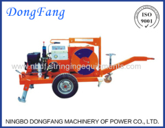
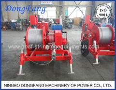
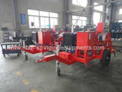
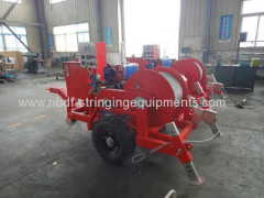
Hydraulic Cable Winch Puller of Underground Cable Laying Equipment
| Min. Order: | 1 Set/Sets |
|---|---|
| Payment Terms: | T/T |
| Supply Ability: | 10 sets per month |
| Place of Origin: | Zhejiang |
Company Profile
| Location: | Ningbo, Zhejiang, China (Mainland) |
|---|---|
| Business Type: | Manufacturer |
Product Detail
| Model No.: | DQ40 |
|---|---|
| Means of Transport: | Ocean |
| Brand Name: | Dongfang |
| Description: | Hydraulic Cable Winch Puller |
| Model: | DQ40 |
| Pulling speed: | 0-12 m/min |
| Diameter of pulling rope: | 11 mm |
| Length of pulling rope: | 650 meters |
| Engine: | Diesel engine |
| Weight: | 2000 kgs |
| Production Capacity: | 10 sets per month |
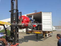
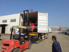
| Packing: | plywood case container |
| Delivery Date: | 45-60 days |
Product Description
4 Ton Hydraulic Cable Winch Puller is used for pulling underground cable with self steel wire rope which is wound on the capstand of puller.

The machine can be painted with different colors.

DQ40 Hydraulic Cable Puller
Item No.: 21135
Technical data:
- Maximum Continuous pulling force (KN): 40
- Pulling speed (m/min): 0-12
- Steel wire rope size (mm): Φ11
- Rope winding capacity (m): 650
- Water cooled Diesel engine: 24 hp /2000 rpm
Features:
- Equipped with Water cooled diesel engine system
- Equipped with hydraulic pump and motor, hydraulic steppless speed control system
- with max. pulling force preset, pulling force could be displayed on the machine. With over-load protect system, the machine will be stopped if the pulling cable get stuck in duct.
- The speed could be displayed digitally, the pull length could be displayed on board.
- With automatic winding system, the winding force could be adjusted.
- With rigid axle for towing
Application: It is used to pull cable in underground cable installation operation.
Dimension (mm): 3670x1800x1500
Weight (kg): 2000

1. Technical Specifications
No. | Descriptions | Data |
1 | Max. Pulling Force (KN) | 40 |
2 | Pulling Speed (m/min) | 0-12 |
3 | Rope Pay out Speed (m/min) | 0-18 |
4 | Length of Pulling rope (m) | Φ11 X 650 |
5 | Diesel Engine Model | 295D |
6 | Power of Diesel Engine (KW) | 17 |
7 | Rotation Speed of Engine (rpm) | 2000 |
8 | Electric System of engine: | DC12V |
9 | Tire model and pressure | 205R14-8 0.4MPa |
10 | Hydraulic pump A10V028DFQ/30RPPA12NOO | 25MPa 28ml/r |
11 | Hydraulic Motor INM1-250BD31 | 25MPa 250ml/r |
12 | Dimension: L x W x H (mm) | 3600 x 1600 x 1460 |
13 | Weight (kg) | 2000 |

OPERATING INSTRUCTIONS
1. General instructions.
FOR THE SAFE OPERATION OF THIS EQUIPMENT:
1) All authorized operators must become familiar with the equipment and all operating and maintenance procedures, and be sure each day that the equipment is in safe operating condition including all guards and safety devices in place, before allowing it to be operated on that day.
2) In case of any problem arising in the operation of this equipment, it is essential that the problem be identified and corrected before continuing operation.
3) Equipment must be isolated when left unattended, to prevent unauthorized use. Misuse can result in personal injury and property damage.

2. Preparations prior to the operation.
(1) Set up of machine.
Set the machine up on level ground, lower the supporting leg for supporting the machine, make sure the input steel rope on the first groove of Bull wheel is lined up with the cable in front, so there is minimum side load on the puller.
Anchor the unit by steel wire rope and chain hoist. Do a test pull up to the maximum rating of the machine against a suitable anchor to prove the machine set up prior to beginning pulling.
In order to protect against electrical hazards due to induction or electrical contact, proper grounding of the machine as per I.E.C and/or other applicable local standards is required.
Diesel Fuel tank: according to Diesel engine operation manual.
Engine oil : according to Engine operation manual.
Engine water tank: according to Engine operation manual.
Hydraulic oil tank: 120 L of L-HM46 Hydraulic oil.
Reducer gear box: 150# Gear oil
Bull Wheels: 150# Gear oil, about 1.5 L/wheel.
(2) Fill the oil level as per following recommended data:
(3) Normal inspection before work
a. Hydraulic oil level (Note: the hydraulic oil level/thermometer is at the side of the oil tank, don't confuse the engine oil tank and diesel oil tank). The hydraulic oil surface should not lower than the oil level;
b. Check the engine oil and fuel in the Diesel Engine. (As per engine Instruction Manual) ;
c. Check the grease on the bull wheels;
d. Check open gears and drives for good lubrication;
e. Check tyres air pressure: the pressure should be 4-5 bar.

1. Start up the machine without load
1) Put the Operation Handle of Hand Operated Direction Valve in Neutral Position.
2) Shut down the Throttle valve, release the Overflow valve by turning it counter clockwise. Start the diesel engine, the Power Switch turns to Working position.
3) Pay out of steel wire rope: Push the handle of Direction Valve forward, Adjust the Throttle valve to control the rotation speed of bull wheels, Turn the Overflow valve to pay out the steel wire rope. When pay out the steel wire rope to suitable position, shut down the Throttle valve.

Please note: When pay out the steel wire rope, the operator should pull the rope tightly before the puller, otherwise the steel wire rope will slide on the bull wheels.
2. Pulling the cable
1) Connect the steel wire rope with head of cable.
2) Pull the cable: Move the handle of direction valve backward, open the Throttle valve, start pulling operation. The Throttle valve controls the pulling speed, and Overflow valve control the maximum pulling force. When the pulling is stopped, shut down the Throttle valve.
3) During the pulling operation, the pulling speed can be controlled by the throttle of diesel engine and Throttle valve. Turn the Throttle valve clockwise , the speed will be faster. Turn the Throttle valve counter clock wise, the speed will be slower.
4) When the pulling force is more than 25KN, the pulling speed should be slower, otherwise the diesel engine will be stopped.
5) The pulling length of cable can be read from the meter, the pulling force also can be read from the pressure gauge.
6) When the pulling operation is completed, shut down the Throttle Valve, release the Overflow Valve, and turn the Throttle of engine into idle condition. Then shut down the engine.

5. Points for Attention.
1) When check the Overflow pressure in the Overflow valve, put the Direction Valve in Neutral position, turn the Throttle valve slowly, when the indicator of pressure guage is stable, the indicated pressure is the pressure of preset pressure.
2) It is strictly forbidden that the Direction Valve to be used for stopping the machine. Because there is big hydraulic impulse in hydraulic system, and the diesel engine will be stopped.
3) The temperature of hydraulic oil can not be higher than 75°C, otherwise the machine have to be stopped.


