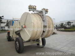
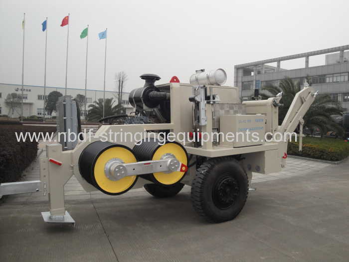
16 Ton Hydraulic Tensioner for Stringing four conductors on 500KV overhead power line
| Min. Order: | 1 Set/Sets |
|---|---|
| Trade Term: | FOB,CFR,CIF |
| Payment Terms: | L/C, T/T |
| Supply Ability: | 10 sets per month |
| Place of Origin: | Zhejiang |
Company Profile
| Location: | Ningbo, Zhejiang, China (Mainland) |
|---|---|
| Business Type: | Manufacturer |
Product Detail
| Model No.: | SA-YZ4X40 |
|---|---|
| Means of Transport: | Ocean |
| Brand Name: | Dongfang |
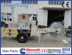
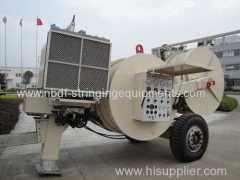
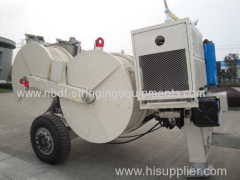
| Overhead Line Equipment: | 16 Ton Hydraulic Conductor Tensioner |
| Model: | SA-YZ4X40 |
| Max. Tension force: | 16 Ton 160 KN |
| Max. Stringing Speed: | 5 km per hour |
| Max. pulling back force: | 16 Ton 4X40 KN |
| Max. pull back speed: | 4X1.2 km per hour |
| Max. diameter of conductor: | 40 mm |
| Quantity of conductors: | 4 or 2 conductors |
| Production Capacity: | 10 sets per month |
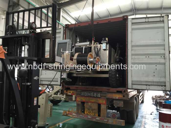
| Packing: | container plywood case |
| Delivery Date: | 30-45 days |
Product Description
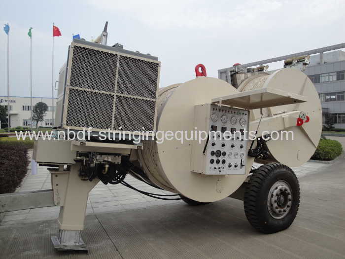
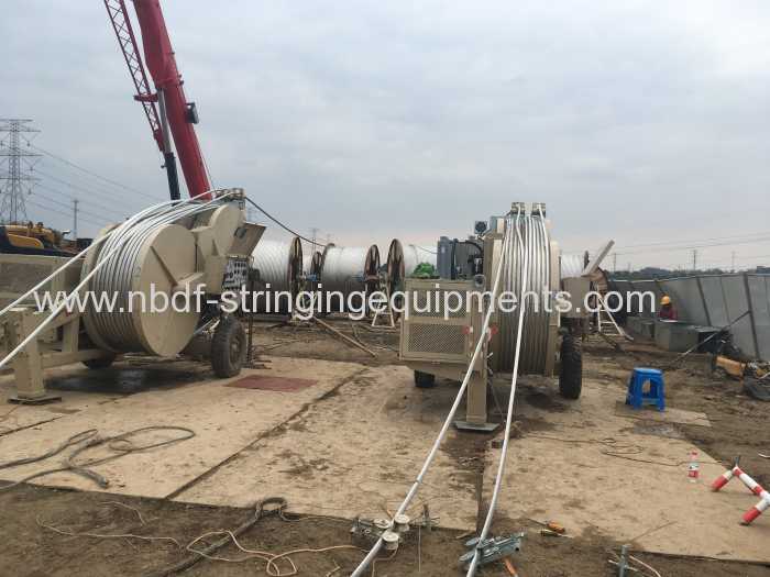
16 Ton Hydraulic Tensioner is used for four or two conductors stringing on 500 KV transmisson line. It is equipped with Water Cooled American Cummins diesel engine and Germany Rexroth hydraulic pump, Italian R.R. reducer, AKG radiator, and Wika Hydraulic instrument.

Ningbo Dongfang Macinery of Power Co., Ltd. designs and manufactures complete range of hydraulic tensioners for overhead transmission line from 1990's. Ningbo Dongfang is the sole manufacture who can provide whole set of tension stringing equipment and tools for the overhead transmission line and underground cable stringing in China. We designed hydraulic conductor tensioner for overhead transmission line up to 24 tons capacity, the big hydraulic conductor tensioner 4 X 60 KN can be used for big conductors stringing up to 45mm diameter, with 4 independent hydraulic motors for driving four sets of bull wheels.
From 1980's, the Chinese engineering companies started using hydraulic conductor tensioner instead of mechanical friction tensioner on transmission line construction. (It is still used in some area and some countries). First, the hydraulic conductor tensions were used in 500KV transmission line, then 220 KV and 330 KV transmission line. Chinese manufacture started to make hydraulic conductor tensioner from the end of 1980, the production level is almost same as the world leading manufacture now.
Compare to the mechanical friction tensioner, the hydraulic conductor tensioner have following features:
1) The Tension force of hydraulic tensioner can be controlled stepless, the tension force is stable in the stringing.
2) The hydraulic system of Tensioner has over load protection system, the max. tension force of conductor tensioner could be pres-set, this function could protect the conductor and reduce the wear of machine parts. The operation prevent the wear of conductors in the stringing, and reduce the electric power loss caused by corona.
3) The cooling system of hydraulic tensioner is also driven by hydraulic oil, it is more efficient and stable.
4) The modern hydraulic conductor tensioners are equipped with high performance discharge pump and hydraulic motors, for setting up closed hydraulic circuit system. The hydraulic reaction speed is very fast and sensitive. Most of hydraulic tensioners also have pulling functions.
5) The hydraulic system also can be electric controlled include the hydraulic pump and hydraulic valve, the tension procedure could be registered by computer, and remote controlled.

Most of Chinese engineering companies are using hydraulic conductor tensioners in their overhead transmission line construction now.
Hydraulic Tensioner 16 Ton capacity
Item No. | 07203 |
Model | SA-YZ4X40 |
Max. Tension Force (KN) | 4X40 or 2 X 80 |
Continuous Tension Force (KN) | 4X35 or 2X 70 |
Max. Line Speed(km/h) | 5 |
Max. Pulling back force (KN) | 4X40 or 2 X 80 |
Max. Pulling back speed (km/h) | 4 x 1.2 |
Diameter of Bullwheel (mm) | Φ1500 |
Number of grooves | 4 X 5 |
Max. Conductor Diameter (mm) | Φ36 |
Model of Engine | Water cooled Cummins |
Power of Engine | 82 KW |
Rotate Speed of Engine (rpm) | 2500 |
Electrical system: | DC24V |
Weight (kg) | 9900 |
Dimension (m) | 5.25x 2.30 x 2.70 |
Application: The machine is used for stringing four or two bundled conductors or steel ropes.
Features:
- Closed hydraulic circuit, infinitely variable pull / tension force control in both directions.
- The max. tension / pull back force for conductor stringing operation can be preset, the tension /pull back force can be read from the tension gauge of machine.
- Spring applied hydraulic released brake acts automatically in case of hydraulic failure to ensure line safety
- Automatic overpull protection system.
- Hydraulic oil cooling system. Hydraulic front jack.
- Bull wheels lined with wear proof MC nylon lining segment.
- Optional 4 hydraulic power outlets to control 4 sets of hydraulic reel stands.
- Mounted on trailer with rigid axle for towing at max. speed of 15 km / h.
Main components:
- Engine: Cummins water cooled engine (USA)
- Main variable displacement pump and main motor: Rexroth (German)
- Reducer: R.R. (Italian)
- Main hydraulic valves: Rexroth (German)
- Hydraulic Instrument: WIKA (German)
- Radiator: AKG (German)
- Quick couplings: EMB (German)
We have designed and manufactured whole series of tensioners for single conductor to six bundled conductors stringing from 33 KV up to 1000 KV transmission line construction.
Our Series of Hydraulic Conductor Tensioner
Model | Max. Tension Force | Usage | Max. Diameter of Conductor |
SA-YZ30A | 30 KN | Single conductor or OPGW | 32 mm |
SA-YZ40A | 40 KN | Single conductor or OPGW | 40 mm |
SA-YZ2X35 | 70 KN | Single or Two Conductors | 32 mm |
SA-YZ2x40 | 80 KN | Single or Two Conductors | 40 mm |
SA-YZ2X50 | 100 KN | Single or Two Conductors | 40 mm |
SA-YZ2X55 | 110 KN | Single or Two Conductors | 40 mm |
SA-YZ2X70 | 140 KN | Single or Two Conductors | 42 mm |
SA-YZ2X80 | 160 KN | Single or Two Conductors | 45 mm |
SA-YZ2X80S | 160 KN | Four or Two conductors | 40 mm |
SA-YZ4X40 | 160 KN | Four or Two conductors | 40 mm |
SA-YZ2X90 | 180 KN | Single or Two Conductors | 45 mm |
SA-YZ4X45 | 180 KN | Four or Two conductors | 40 mm |
SA-YZ4X50 | 200 KN | Four or Two conductors | 45 MM |

SA-YQ180 Hydraulic Puller
Item No. | 07051 |
Model | SA-YQ180 |
Stringing capacity | 1 pilot steel wire rope |
Max. Pulling Force (KN) | 180 |
Max. Continuous Pulling Force (KN) | 160 |
Speed at Max. continuous pull: | 2.5km/h |
Max. Pulling Speed (m/min) | 5km/h |
Root Diameter of Bull wheel (mm) | Φ630 |
Number of grooves | 9 |
Max. Steel rope Diameter (mm) | Φ24 |
Model of Diesel Engine | Water cooled diesel engine |
Power of Diesel Engine | 209 KW |
Rotate Speed of Engine (rpm) | 2100 |
Electrical System | DC24V |
Weight (kg) | 7500 |
Dimension (m) | 5.5 x 2.17 x 2.57 |
Application: The hydraulic puller is used to pull four bundled conductors or 2 bundled conductors for power line construction. It is fully hydraulic controlled, easily used and maintained
Features:
- Closed hydraulic circuit,infinitely variable speed control in both rotating directions.
- The max pulling force for stringing operation can be preset, pulling force in the rope can be read on the line pull gauge.
- Automatic over pulling protection system
- Spring applied hydraulic released brake acts automatically in case of hydraulic failure to ensure safety.
- Hydraulic oil cooling system.
- Heat treated wear-proof bull wheels
- With rigid axle for towing at high speed, the machine looks beautiful.
- Hydraulic actuated pulling rope clamp for convenient reel change.
- Integral self-loading reel winder with automatic level wind.
Main Components:
- Engine: Cummins water-cooled diesel engine. (USA)
- Main variable displacement hydraulic pump and main motor: Rexroth (German)
- Reducer: Rexroth. (Germany)
- Reel winder motor: Danfoss (Danish)
- Main hydraulic valves: Rexroth (Germany
- Hydraulic instruments: WIKA (German)
- Radiator: AKG (German)
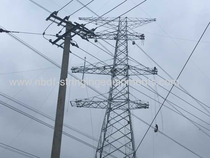
5 Sheaves Stringing Blocks for four bundled conductors
Item No. | Model | Working Load (KN) | Conductor Range (mm) | Material of sheave | Weight (kg) |
10143 | SHWQN822 | 120 | ≤36 mm | All Nylon | 170 |
Application: It is used for four bundled conductors stringing. Sheave size: Ø822 X Ø710 X 110
All the conductor sheaves are made of high strength nylon, the central sheave is specially designed with high strength, it is good for passing both of pilot steel wire rope and conductors.
All the sheaves are mounted on high strength heavy duty ball bearings.
The frame of stringing blocks is made of galvanized steel. Breaking Load: 3 Times of working load.
Option: The central sheave can be changed to steel sheave.
6. Balance Running Board for four bundled conductors
Item No. | Model | Working Load (KN) | Pulley Size (mm) | Conductor Condition | Weight (kg) |
17231 | SZ4A-13 | 130 | Φ660 X 100 | 4 bundled conductors | 139 |
Application: The Head board is used for pulling 4 bundled conductors.
The whole set is included one of 13 ton head swivels (connected with pilot steel wire rope ) and four of 5 ton swivel joints(connected with conductor grips).
The steel wire rope is going through the centre pulley to connect four conductors.

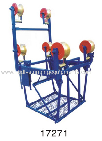
AERIAL TROLLEY FOR WORKING ON 4 BUNDLED CONDUCTORS
Item No. | Model | Rated Load (KN) | Max. dia. of conductor passed through (mm) | Weight (kg) | Remark |
17271 | SFS1 | 1.5 | Φ70 | 40 | Distance 450 , 500 mm |
Descriptions: It is used for work and maintenance on overhead four conductors.
There is mechanical brake system for the cart to stop on the line.
Please inform the distance between conductors when confirm the order.
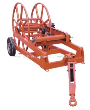
5.1.1 Reel winders
5.1.1.1 Overview
Reel winders are used to wind up a pulling rope behind bullwheel pullers. They are not required for drum pullers.
Reel winders are usually incorporated on the same frame as the bullwheel pullers, but sometimes, for larger pullers, the reel winder is a completely separate machine to reduce the overall weight of each component.
They can have their own power source for driving the rope drum, or more frequently they may be powered from a hydraulic drive on the puller by means of hydraulic hose connections.
In any case, they are always driven so that they tend to wind up the pulling rope faster than the puller is able to feed the rope to the reel winder. This ensures that the pulling rope always remains taut between the puller and the reel winder so that the rope does not loosen on the puller bullwheels.
5.1.1.2 Criteria for choosing reel winders
The criteria for choosing reel winders are as follows.
a) Reel winders have a levelwind system to help to wind the pulling rope evenly across the rope drum and prevent uneven build-up that could cause snarling of the rope on the drum.
b) The reel winder should be able to accommodate the size and weight of the pulling rope drum to be used on the project. Normally the rope lengths to be used on the project are multiple, and therefore the reel is changed when full of rope and replaced with a new one empty; in this case the pulling rope is provided with proper connector to detach or connect between the single section lengths. Larger reels will reduce or eliminate the need to change reel every section or rope, but will increase the overall weight of the reel winder.
c) The reel winder circuit is normally arranged to allow the stringing process when the pulling rope is being installed from the puller end to the tensioner end of the pull section, to prevent the rope drum from continuing to turn when the rope pulling operation has stopped. In some case the take-up drive can be disconnected, and this requires an overspin mechanical brake on the transmission.
d) There shall be a holding brake or reverse motion brake incorporated in the reel winder drive train so as to hold the pulling rope at normal tension between the reel winder and the puller bullwheels in case of a drive train failure, or during a normal stop sequence.
e) If the reel winder is not an integral part of the puller, the reel winder frame should incorporate adequately sized anchor lugs for attachment of anchors to hold the machine in place on the job site. Since separate reel winders are typically trailer mounted, and will move easily on wet or unstable earth, holding anchors are strictly required.
f) If the reel winder is not an integral part of the puller, the reel winder frame shall incorporate an earthing lug or bar, free of paint or other coating or surface contamination which would prevent a good electrical connection, specifically when attaching an earth clamp.
5.4.5 Reel stands
5.4.5.1 General
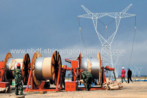
Reel stands are used to hold the conductor reels. They are usually positioned behind the tensioner, and used to wind off the conductor from the reel as it is fed to the tensioner. They can be self-loading, and therefore called reel-elevators, but usually the reels are loaded into the reel stands by crane, or other lifting means.
One reel stand is required for each subconductor of the phase.
For distribution lines reel stands or reel carriers are used to hold the conductor reels. They can be used to directly tension the distribution conductor when such conductors are very small (less than 13 mm) and there is no possibility of contact between the new conductor being installed and existing energized conductors.
Reel stands are rarely incorporated on the same frame as the tensioner, but usually only for single conductor tensioners.
The reel stand will require a brake to hold a tension in the conductor between the reel stand and the tensioner. This brake should be of sufficient size to hold this tension at normal stringing speeds until the reel has been emptied of conductor. Hydraulic braking systems are preferred in order to reduce jerking or bouncing at the conductor, and normally the drive system is fed directly by the tensioner machine.
5.4.5.2 Criteria for choosing reel stands
Criteria for choosing reel stands are as follows.
a) The reel stand shall be able to accommodate the size and weight of the conductor reel to be used on the project.
b) The reel stand frame should incorporate adequately sized anchor lugs for attachment of earth anchors to hold the machine in place on the job site. Anchor lugs and anchors are especially required if the reel stands are trailer mounted, since wheeled trailers will move easily on wet or unstable earth.
c) The reel stand frame shall incorporate an earthing lug or bar, free of paint or other coating or surface contamination which would prevent a good electrical connection, specifically when attaching an earth clamp.
