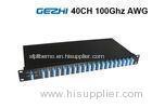
40ch 100G Thermal AWG
| Min. Order: | 1 Piece/Pieces |
|---|---|
| Payment Terms: | T/T |
| Supply Ability: | 40000Channel/Month |
| Place of Origin: | Guangdong |
Company Profile
| Location: | Shenzhen, Guangdong, China (Mainland) |
|---|---|
| Business Type: | Manufacturer |
| Main Products: | Fiber Passive Component, CWDM, DWDM, Coupler, Switch |
Product Detail
| Model No.: | 100GTAWG |
|---|---|
| Means of Transport: | Air |
| Brand Name: | Flyin |
| Number of Channels: | 40 |
| Number Channel Spacing: | 100GHz |
| Adjacent Channel Isolation: | 25dB |
| Non-Adjacent, Channel Isolation: | 30dB |
| Total Channel Isolation: | 22dB |
| Insertion Loss Uniformity: | 1.0~1.5dB |
| Insertion Loss Ripple: | 0.5dB |
| Optical Return loss: | 40dB |
| Production Capacity: | 40000Channel/Month |
| Packing: | standard packing |
| Delivery Date: | 7working days |
Product Description
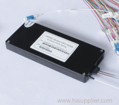
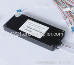
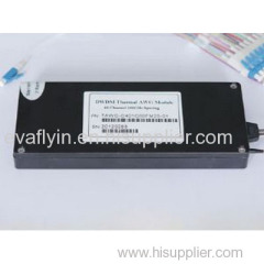
Flyin Optronics offers a full range of Thermal/Athermal AWG products, including 50GHz, 100GHz and 200GHz Thermal/Athermal AWG. Here we present the generic specification for the 40-channel 100GHz Flat Top Thermal AWG (40 channel TAWG) MUX/DEMUX component supplied for use in DWDM system.
Flyin's 40 channel 100G Thermal AWG(100G TAWG) is designed for use within the C -band release of DWDM system. To decrease the power dissipation of the devices in different environmental conditions, the TAWG package is special designed with selection of reliable thermal plastic with low thermal conduction, and the TAWG operating temperature is controlled by using foil resist heater or Peltier TEC with thermistor temperature sensor. Different input and output fibers, such as SM fibers, MM fibers and PM fiber can be selected to meet different applications. We can also offer different product packages, inluding special metal box and 19" 1U rackmount.
The planar DWDM components(Thermal/Athermal AWG) from Flyin Optronics are fully qualified according to Telcordia reliability assurance requirements for fiber optic and opto-electronic components (GR-1221-CORE/UNC, Generic Reliability Assurance Requirements for Fiber Optic Branching Components, and Telcordia TR-NWT-000468, Reliability Assurance Practices for Opto-electronic Devices).
Optical Specification (Flat Top Thermal AWG)
Parameters | Condition | Specs | Units | ||
Min | Typ | Max | |||
Number of Channels | 40 | ||||
Number Channel Spacing | 100GHz | 100 | GHz | ||
Cha. Center Wavelength | ITU frequency. | C -band | nm | ||
Clear Channel Passband | ±0.1 | nm | |||
Wavelength Stability | Maximum range of the wavelength error of all channels and temperatures in average polarization. | ±0.05 | nm | ||
-1 dB Channel Bandwidth | Clear channel bandwidth defined by passband shape. For each channel | 0.4 | nm | ||
-3 dB Channel Bandwidth | Clear channel bandwidth defined by passband shape. For each channel | 0.6 | nm | ||
Optical Insertion Loss at ITU grid | Defined as the minimum transmission at ITU wavelength for all channels. For each channel, at all temperatures and polarizations. | 4.5 | 6.0 | dB | |
Adjacent Channel Isolation | Insertion loss difference from the mean transmission at the ITU grid wavelength to the highest power, all polarizations, within the ITU band of the adjacent channels. | 25 | dB | ||
Non-Adjacent, Channel Isolation | Insertion loss difference from the mean transmission at the ITU grid wavelength to the highest power, all polarizations, within the ITU band of the nonadjacent channels. | 30 | dB | ||
Total Channel Isolation | Total cumulative insertion loss difference from the mean transmission at the ITU grid wavelength to the highest power, all polarizations, within the ITU band of all other channels, including adjacent channels. | 22 | dB | ||
Insertion Loss Uniformity | Maximum range of the insertion loss variation within ITU across all channels, polarizations and temperatures. | 1.0 | 1.5 | dB | |
Directivity(Mux Only) | Ratio of reflected power out of any channel(other than channel n)to power in from the input channel n | 40 | dB | ||
Insertion Loss Ripple | Any maxima and any minima of optical loss across ITU band, excluding boundary points, for each channel at each port | 0.5 | dB | ||
Optical Return loss | Input & output ports | 40 | dB | ||
PDL/Polarization Dependent Loss in Clear Channel Band | Worst-case value measured in ITU band | 0.3 | 0.5 | dB | |
Polarization Mode Dispersion | 0.5 | ps | |||
Maximum Optical Power | 23 | dBm | |||
MUX/DEMUX input/ output Monitoring range | -35 | +23 | dBm | ||
IL Represents the worst case over a +/-0.1nm window around the ITU wavelength
PDL was measured on average polarization over a +/- 0.1nm window around the ITU wavelength.
Ordering Information
AWG | X | XX | X | XXX | X | X | X | XX |
Band | Number of Channels | Spacing | 1st Channel | Filter Shape | Package | Fiber Length | In/Out Connector | |
C=C-Band L=L-Band D=C+L-Band X=Customize | 16=16-CH 32=32-CH 40=40-CH 48=48-CH XX=Special | 1=100G 2=200G 5=50G X=Special | C60=C60 H59=H59 C59=C59 H58=H58 XXX=special | G=Gaussian B=Broad Gaussiar F=Flat Top | M=Module R=Rack X=Special | 1=0.5m 2=1m 3=1.5m 4=2m 5=2.5m 6=3m S=Specify | 0=None 1=FC/APC 2=FC/PC 3=SC/APC 4=SC/PC 5=LC/APC 6=LC/PC 7=ST/UPC S=Specify |