

Industrial Automatic Control Pipeline Valves For Guiding Pulp , Y - Ball Valve
| Place of Origin: | Zhejiang |
|---|
Company Profile
| Location: | Yantai, Shandong, China (Mainland) |
|---|---|
| Business Type: | Manufacturer |
Product Description
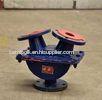
Industrial Automatic Control Pipeline Valves For Guiding Pulp , Y - Ball Valve
Control Automatic Y-Ball Valve Pipeline Valves For Guiding Pulp
Quick Detail:
1. The service life is three times longer than the same kind of products
2. Rubber balls are added to improve the abrasion resistance
3. The ideal device for liquor containing solid particles and consisting of liquid-solid and gas-solid
Description:
1. The inner of upper and lower valves are lined with our patent rubber, which prolongs the service life as 3 times long as conventional product.
2. Between the upper and lower valve there is a rubber ball which facilitates seal and averts the same site from being repeatedly abraded. The rubber ball advantages are as follows:
(1) The conventional Y-ball valve adopts plane seal which is subject to impact of ore pulps for such a long time that the sealing function is damaged. The adoption of rubber ball precludes the same site from being repeatedly abraded.
(2) The interior of rubber ball is propped with frame and the exterior of rubber ball is vulcanized and shrouded with rubber. This design greatly extends the valve service life.
3. In the inner of valve there are two guide ways whose function is to usher rubber ball from one feeding opening to another opening by these guide ways.
Applications:
It is used for ore pulps, slag, tailings, sewage and chemically corrosive mediums.
Principle:
Y-ball valves have an L- or T-shaped hole through the middle. The different combinations of flow are shown in the figure. It is easy to see that a T valve can connect any pair of ports, or all three, together, but the 45 degree position which might disconnect all three leaves no margin for error. The L valve can connect the center port to either side port, or disconnect all three, but it cannot connect the side ports together.
Specifications :
| Specification (DN) | A | B | C | Flange Dimension | ||
| Center distance of bolt holes | Outside diameter of flange | n-Φd | ||||
| 65 | 247 | 227 | 197 | 145 | 185 | 4-Φ18 |
| 80 | 267 | 250.5 | 217 | 160 | 200 | 8-Φ18 |
| 100 | 308.5 | 296 | 256.5 | 180 | 220 | 8-Φ18 |
| 125 | 352 | 346 | 300 | 210 | 250 | 8-Φ18 |
| 150 | 410 | 400 | 346.5 | 240 | 285 | 8-Φ22 |
| 200 | 477 | 476.5 | 413 | 295 | 340 | 8-Φ22 |
| 250 | 569 | 569 | 493 | 350 | 395 | 12-Φ22 |
| 300 | 656 | 669.5 | 580 | 400 | 445 | 12-Φ22 |
| 350 | 735 | 761 | 659 | 460 | 505 | 16-Φ22 |
| 400 | 833.5 | 863 | 747.5 | 515 | 565 | 12-Φ26 |
| 450 | 922.5 | 952 | 824.5 | 565 | 615 | 20-Φ26 |
| 500 | 1011 | 1054 | 913 | 620 | 670 | 20-Φ26 |