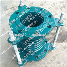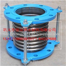
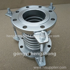
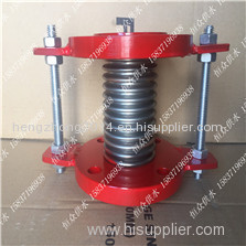
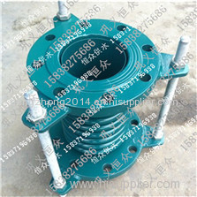
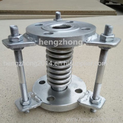
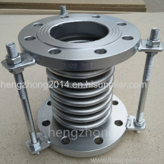
Flange connection bellow compenstor
| Min. Order: | 1 Piece/Pieces |
|---|---|
| Trade Term: | FOB,CIF |
| Payment Terms: | Paypal, D/P, D/A, T/T, cash |
| Supply Ability: | 452300 pieces |
| Place of Origin: | Henan |
Company Profile
| Location: | Zhengzhou, Henan, China (Mainland) |
|---|---|
| Business Type: | Manufacturer, Trading Company |
Product Detail
| Model No.: | JDZ |
|---|---|
| Means of Transport: | Ocean, Air, Courier, Land |
| Connection: | Flange |
| Shape: | Equal |
| Head Code: | Square |
| Technics: | Forged |
| Material: | Carbon Steel |
| Type: | Coupling |
| Brand Name: | gongyi hengzhong |
| Production Capacity: | 452300 pieces |
| Packing: | wooden box package |
| Delivery Date: | 15days |
Product Description
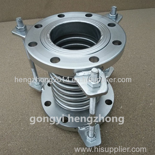
Corrugated compensators, also known as expansion joints, or expansion joints. The utility model is composed of a bellows (a kind of elastic element), an end pipe, a bracket, a flange, a conduit and other accessories that form the main body of its work. Mainly used in a variety of pipelines, it can compensate the thermal displacement of the pipeline, mechanical deformation and absorption of various mechanical vibration, play a role in reducing the deformation stress and improve the service life of the pipeline. Corrugated compensator connection is divided into two types: flange connection and welding. Straight buried pipe compensator generally adopts welding method (except trench installation)
Welding process:
1. The internal and external diameter of the straight side section of the bellows shall meet the requirements of GB1804 H12.
2. The size and technical requirements of connecting flange and end pipe of corrugated compensator and pipeline (or equipment) shall meet the corresponding standards. When the end pipe is connected, the pipe ends shall be beveled at 30 2.5.
3. When the end pipe of the corrugated compensator is a steel plate rolled electric welded pipe, the tolerance of length and roundness around the outer end of the end pipe shall conform to the tolerance table.
4. The girth welds connecting the bellows with the end pipe (or flange) shall be tig welding or FGFC welding, and the single layer wall thickness of the bellows shall be greater than 2mm by arc welding.
5. Protection measures shall be taken for the bellows when assembling the bellows compensator to prevent welding arc from burning through the bellows and welding slag from splashing on the bellows. The welding seam of each part of expansion joint (compensator) shall not have cracks, pores, slag inclusion and other defects, and the undercut depth shall not be greater than 0.5mm.
6. After the pressure weld of the corrugated compensator is welded, the pressure test shall be carried out on the pressure weld, and the test pressure shall be 1.5 times of the design pressure. According to the volume size of the expansion joint (compensator), keep the pressure for 10-30min, check whether there is leakage in all parts of the expansion joint (compensator), and the ratio between the maximum wave distance and the wave distance before compression shall not exceed 1.15.
7. The appearance and geometric dimensions of the compensator shall be inspected after welding. Coaxiality tolerance of two end faces of compensator; When the nominal diameter is less than or equal to 500mm, it is 5mm; When the nominal diameter is greater than 500mm, it is 1% of the nominal diameter and less than or equal to 10mm. The verticality tolerance between the two end faces of the compensator and the spindle is 1% of the nominal diameter and less than or equal to 3mm. The inspection of expansion joint (compensator) before delivery mainly includes the above appearance inspection, geometric dimension inspection and pressure inspection. For expansion joints (compensators) with special requirements, other inspection methods, such as air tightness test, leakage and coloring, nondestructive inspection, etc. can be carried out according to the working conditions, process requirements, etc. as agreed by the supplier and the supplier.
Installation and use:
1. Before installation, the compensator should check its model, specification and pipeline configuration, which must meet the design requirements.
2. For the compensator with inner sleeve, the direction of inner sleeve bobbin should be consistent with the direction of medium flow, and the rotation plane of hinge type compensator should be consistent with the rotation plane of displacement.
3, the need for "cold tight" compensator, pre-deformation of the auxiliary components used in the pipeline installation should be completed before removal.
4. It is strictly prohibited to adjust the installation out-of-tolerance of pipes by means of deformation of corrugated compensator, so as not to affect the normal function of compensator, reduce the service life and increase the load of pipe system, equipment and supporting members.
5. During installation, welding slag is not allowed to splash on the surface of the wave shell, and the wave shell is not allowed to suffer other mechanical damage.
6. After the installation of the pipe system, the yellow auxiliary positioning components and fasteners used for installation and transportation on the corrugated compensator shall be removed as soon as possible, and the limit device shall be adjusted to the specified position according to the design requirements, so that the pipe system has sufficient compensation ability under environmental conditions.
7. All the active components of the compensator shall not be jammed or restricted by external components, and the normal operation of each active part shall be guaranteed.
8. During the water pressure test, the secondary fixed pipe rack equipped with the pipe end of compensator shall be strengthened to prevent the pipe from moving or rotating. For the compensator used for gas medium and its connecting pipeline, pay attention to whether temporary support is needed when filling water. The content of 96 chloride ion in the water cleaning solution did not exceed 25PPM.
9. After the water pressure test, the water in the wave shell shall be drained as soon as possible, and the inner surface of the wave shell shall be quickly blown dry.
10. The insulation material in contact with the bellows of the compensator shall be chlorine-free.
Performance characteristics:
1, small size, light weight, good flexibility, easy installation and maintenance.
2, the installation can produce transverse, axial, angular displacement, not by the pipe impaction, flange uneven restrictions.
3, the structure can reduce the transmission noise, strong vibration absorption ability.
Application: flexible rubber joint is widely used in chemical engineering, architecture, water supply, drainage, petroleum, heavy and light industry, freezing, sanitation, water heating, fire protection, electric power and other basic engineering because of its good comprehensive performance.
Technical parameters:
Diameter DN | Number of wave | Pressure grade Mpa | Available area of bellows c㎡ | Max size of external diameter mm | Length | |||||
0.25 | 0.6 | 1.0 | 1.6 | 2.5 | Flange JDZ/F(mm) | connection tube JDZ/F(mm) | ||||
Axial compensation mm,f911N/ram | ||||||||||
32 | 8 | 25/21 | 22/26 | 20/26 | 18/63 | 15/98 | 16 | 110 | 160/250 | 264/210 |
16 | 50/11 | 46/14 | 41/14 | 36/32 | 31/47 | 220 | 224/291 | 316/320 | ||
40 | 8 | 25/28 | 22/44 | 20/44 | 18/89 | 15/106 | 23 | 130 | 164/259 | 269/260 |
16 | 50/14 | 46/22 | 41/22 | 36/45 | 31/55 | 240 | 230/304 | 319/400 | ||
50 | 8 | 25/30 | 22/51 | 20/70 | 18/70 | 15/138 | 37 | 150 | 172/276 | 282/230 |
16 | 50/16 | 46/26 | 41/35 | 36/35 | 31/70 | 260 | 240/342 | 347/450 | ||
65 | 8 | 33/28 | 30/35 | 26/44 | 22/55 | 19/68 | 55 | 170 | 315/294 | 300/260 |
12 | 42/16 | 38/22 | 38/32 | 34/40 | 29/50 | 280 | 260/334 | 340/470 | ||
80 | 8 | 40/20 | 36/26 | 34/33 | 28/41 | 24/54 | 81 | 200 | 240/338 | 344/260 |
10 | 53/14 | 49/17 | 49/21 | 43/26 | 38/33 | 230 | 270/368 | 374/300 | ||
100 | 8 | 45/47 | 45/60 | 40/75 | 35/93 | 29/117 | 121 | 220 | 235/317 | 323/280 |
10 | 76/26 | 74/32 | 64/40 | 57/50 | 49/63 | 260 | 305/381 | 387/320 | ||
125 | 6 | 48/38 | 42/47 | 38/59 | 34/74 | 29/92 | 180 | 250 | 282/314 | 316/320 |
8 | 85/23 | 77/29 | 66/36 | 58/45 | 50/56 | 290 | 382/386 | 388/360 | ||
150 | 6 | 49/42 | 44/50 | 40/62 | 34/78 | 29/97 | 257 | 250 | 282/339 | 338/320 |
8 | 79/34 | 71/43 | 64/51 | 54/59 | 46/65 | 290 | 356/399 | 402/360 | ||
200 | 6 | 52/49 | 46/55 | 42/68 | 38/78 | 34/111 | 479 | 300 | 280/348 | 348/370 |
8 | 73/31 | 65/44 | 59/52 | 53/58 | 48/78 | 340 | 340/402 | 402/420 | ||
250 | 6 | 72/30 | 63/34 | 59/42 | 52/45 | 47/55 | 769 | 300 | 315/379 | 415/420 |
8 | 108/16 | 97/21 | 87/35 | 79/39 | 71/47 | 360 | 393/459 | 493/460 | ||
300 | 6 | 72/51 | 65/55 | 59/59 | 52/65 | 47/71 | 1105 | 340 | 366/427 | 466/488 |
8 | 108/32 | 97/35 | 87/37 | 79/41 | 71/45 | 400 | 464/525 | 564/520 | ||
350 | 6 | 72/58 | 65/62 | 59/67 | 52/74 | 47/81 | 1307 | 340 | 397/452 | 497/480 |
8 | 10/38 | 7/41 | 87/44 | 79/48 | 71/47 | 420 | 509/564 | 609/540 | ||
400 | 6 | 72/54 | 65/58 | 59/62 | 52/68 | 47/75 | 1611 | 340 | 412/478 | 512/480 |
8 | 108/36 | 97/39 | 87/43 | 79/47 | 71/52 | 420 | 522/588 | 622/560 | ||
450 | 6 | 108/32 | 97/35 | 87/37 | 79/41 | 71/45 | 1972 | 340 | 403/498 | 503/500 |
8 | 162/20 | 145/22 | 131/23 | 118/25 | 106/28 | 450 | 503/658 | 603/590 | ||
500 | 6 | 108/59 | 97/64 | 87/68 | 79/75 | 71/82 | 2445 | 340 | 431/523 | 531/500 |
8 | 162/34 | 145/37 | 131/39 | 118/43 | 106/48 | 450 | 531/665 | 631/600 | ||
600 | 6 | 108/74 | 97/80 | 87/85 | 79/94 | 71/103 | 3534 | 380 | 478/548 | 578/540 |
8 | 162/42 | 145/45 | 131/49 | 118/53 | 106/60 | 658/679 | 758/640 | |||
700 | 4 | 108/67 | 97/72 | 87/77 | 79/85 | 71/95 | 4717 | 1110 | 490 | 550 |
6 | 162/42 | 145/45 | 131/49 | 118/53 | 106/60 | 690 | 670 | |||
800 | 4 | 120/88 | 108/95 | 102/102 | 94/112 | 82/123 | 5822 | 1265 | 502 | 560 |
6 | 183/67 | 164/72 | 156/77 | 144/85 | 125/93 | 610 | 600 | |||
900 | 4 | 120/84 | 108/90 | 102/97 | 94/107 | 82/117 | 7620 | 1186 | 620 | |
6 | 183/60 | 164/65 | 156/69 | 144/76 | 125/84 | 720 | ||||
1000 | 4 | 120/91 | 108/98 | 102/105 | 94/166 | 9043 | 1286 | 690 | ||
6 | 183/59 | 164/65 | 156/71 | 144/81 | 790 | |||||
