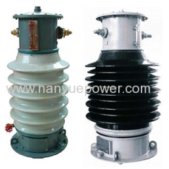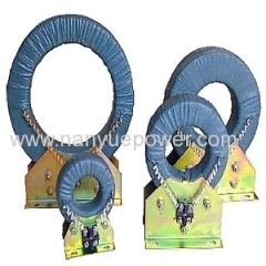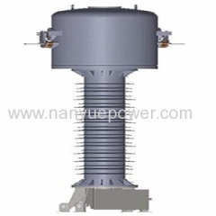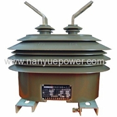
Model LW Current Transformer
| Min. Order: | 1 Set/Sets |
|---|---|
| Trade Term: | FOB,CFR,CIF,EXW |
| Payment Terms: | Paypal, L/C, T/T, WU |
| Supply Ability: | 100000 |
| Place of Origin: | Yunnan |
Company Profile
| Location: | Kunming, Yunnan, China (Mainland) |
|---|---|
| Business Type: | Manufacturer |
Product Detail
| Model No.: | Model LZZW |
|---|---|
| Means of Transport: | Ocean, Land |
| Brand Name: | Nanyue |
| Production Capacity: | 100000 |
| Packing: | Export Standard package |
| Delivery Date: | Delivery in 5 work days after payment |
Product Description
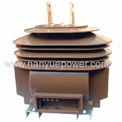
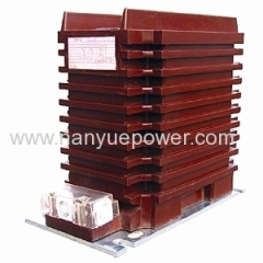
LZZW-12 Current Transformer
Summary
The supporting-type current instrument transformers LZZW-12 are fully enclosed and cast in epoxy resin. The transformers are designed for electric power systems of 50Hz/60Hz rated frequency and 12kV rated voltage. They are used for outdoor mounting. The performances of the products meet standards IEC60044-1 and GB1208-2006. The products are applied to metering electric energy, voltage controlling and relay protection.
Ambient condition
1. Ambient temperature: -25 ~ 40 degrees;
Note: By customize manufacture, the ambient temperature can be as low as -40 degrees.
2. Altitude:≦ 1000m;
3. Pollution class: IV;
Model
Technical specification
1. Rated insulation level: 12/42/75kV.
2. Rated secondary winding current: 5A / 1A.
3. The rated current and accuracy class are displayed in the table below.
4. Partial discharge (PD) level meets standard IEC60044-1.
5. When transformer is working with computer, the lower limit of secondary load can be as low as 1VA for accuracy class 0.2 and 0.5.
Structure feature
1. Cores and windings are cast together in epoxy resin.
2. The transformer cores are manufactured of high-grade magnetic material.
3. The transformer is fixed to the base plate by four screws.
4. The bolted earthed clamp is located on the transformer base plate.
5. The secondary terminals are covered with a protective cover.
6. As the high level of insulation, it can work normally in damp and Pollution II condition.
7. The cores and windings are cast together.
8. Three optional ways of installation, correspondent to product version of A/B/C.
9. The outlet terminals of the primary winding and secondary winding, are respectively marked as P1, P2 and S1, S2.
10. The case that, primary current runs from P1 to P2 and secondary current flows from S1 to S2 through external circuit, is called subtractive polarity. The secondary circuit should not be open, when primary current is flowing. Otherwise, a high voltage will be generated.
11. The transformers are equipped with primary winding and secondary windings. The win dings are fixed to the iron core bar by casting,
12. For the two secondary windings, the first one is for either measuring or protection purposes; the other is for being connected into an open-delta connection in a three-phase system.
13. The outlet of the primary winding is insulated from the earth to a correspondent level.
14. The secondary terminal board is covered with a transparent cover made of plastic.
Rated
voltage
ratio(V)Accuracy
classes
combinationRated output(VA)1S thermal
current(KA)Rated dynamic
current(ka)0.2S0.20.5S0.510P10500.2S
0.5S
0.2
0.5S
10P101010151515922.5751537.510018451502562.520028703004010040040100500601306006013063060130


