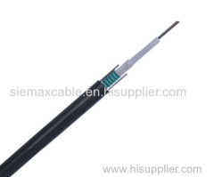
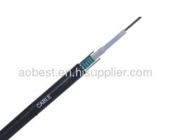
GYFTC8S-8 Optical fiber Cable
| Payment Terms: | T/T |
|---|---|
| Place of Origin: | Zhejiang |
Company Profile
| Location: | Ningbo, Zhejiang, China (Mainland) |
|---|---|
| Business Type: | Manufacturer, Service |
| Main Products: | Electronic |
Product Detail
| Model No.: | GYFTC8S-8 |
|---|---|
| Means of Transport: | Ocean, Land |
| Mode field diameter (1310nm): | 9.2mm±0.4mm |
| Mode field diameter (1550nm): | 10.4mm±0.8mm |
| Cladding diameter: | 125mm±1.0mm |
| Coating diameter: | 245mm±7mm |
| Cut off wavelength of cabled fiber (lcc): | 1260nm |
| Attenuation at 1310nm: | 0.35dB/km |
| Attenuation at 1550nm: | 0.21dB/km |
| Bending loss at 1550nm (100 turns, 30mm radius): | 0.05dB |
| Dispersion in the range 1288 to 1339nm: | 3.5ps/(nm•km) |
| Dispersion at 1550nm: | 18ps/(nm•km) |
Product Description
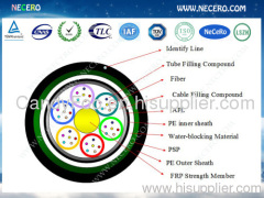
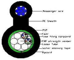
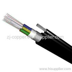
1. Cable cross-section

2. Cable Specification
2.1 Introduction
The fibers are placed in a loose tube made of PBT. The tubes are filled with a water-resistant filling compound. A steel wire locates in the center of core as a metallic strength member. The tubes (and fillers) are stranded around the strength member into a compact and circular cable core. After PSP is applied around the cable core , this part of cable accompanied with the stranded wires as the supporting part are completed with a PE sheath to be figure 8 structure. This kind of cable is specifically applied for self-supporting aerial installation.
2.2 Fiber color code
Fiber color in each tube starts from No. 1 Blue.
1 | 2 | 3 | 4 | 5 | 6 | 7 | 8 | 9 | 10 | 11 | 12 |
Blue | Orange | Green | Brown | _ | _ | _ | _ | _ | _ | _ | _ |
2.3 Color codes for loose tube & filler rod
Tube color in each layer starts from No. 1 Blue. If there are fillers, the color is nature.
1 | 2 | 3 | 4 | 5 | 6 | 7 | 8 | 9 | 10 | 11 | 12 |
Blue | Orange | _ | _ | _ | _ | _ | _ | _ | _ | _ | _ |
2.4 Cable structure and parameter
SN | Item | Unit | Value |
1 | No. of fibers | count | 8 |
2 | No. of fibers per tube(max) | count | 4 |
3 | No. of elements | count | 2 |
4 | Tube diameter | mm | 1.8 |
5 | Outer sheath wall thickness | mm | 2 |
6 | Cable diameter | mm | 19.5*10.8 |
7 | Cable weight | kg/km | 220 |
8 | Short term tension | N | 8000 |
9 | Short term crush | N/100mm | 1000 |
Note: Mechanical sizes are nominal values.
3. Characteristic of Optical Cable
Mechanicalcharacteristic and test method | |||
Tensilestrength | conform to IEC 794-1-E1 | ||
Crush | conform to IEC 794-1-E3 | ||
Impact | conform to IEC 794-1-E4 | ||
Repeatedbending | conform to IEC 794-1-E6 | ||
Torsion | conform to IEC 794-1-E7 | ||
Flexing | conform to IEC 794-1-E8 | ||
Cablebend | conform to IEC 794-1-E11 | ||
Waterpenetration | conform to IEC 794-1-F5B | ||
Temperaturerequirement | Operation | - 40℃ ~ +60℃ | |
Installation | - 10℃ ~ +60℃ | ||
Storage/transportation | - 40℃ ~ +60℃ | ||
Temperaturecycling test | conform to IEC 794-1-F1 | ||
BendingRadius | unloaded | 10times of outer diameter | |
loaded | 20times of outer diameter | ||
4. Characteristic of Optical Fiber
G652D fiber information
| Mode field diameter (1310nm): | 9.2mm±0.4mm |
| Mode fielddiameter (1550nm): | 10.4mm±0.8mm |
| Claddingdiameter: | 125mm±1.0mm |
| Coatingdiameter: | 245mm±7mm |
| Cut offwavelength of cabled fiber (lcc): | £1260nm |
| Attenuationat 1310nm: | £0.35dB/km |
| Attenuationat 1550nm: | £0.21dB/km |
| Bending loss at 1550nm (100 turns, 30mm radius): | £0.05dB |
| Dispersion inthe range 1288 to 1339nm: | £3.5ps/(nm•km) |
| Dispersion at1550nm: | £18ps/(nm•km) |
| Dispersionslope at zero dispersion wavelength: | £0.092ps/(nm2•km) |



.jpg)
