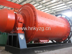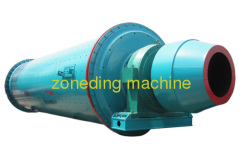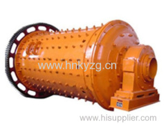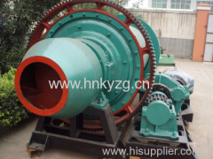
Grate Type Ball Mill
90000.0 USD
| Min. Order: | 1 Set/Sets |
|---|---|
| Payment Terms: | L/C, D/A, T/T |
| Place of Origin: | Shanghai |
Company Profile
| Location: | Shanghai, China (Mainland) |
|---|---|
| Business Type: | Manufacturer |
| Main Products: | Mining Equipment (Beneficiation Equipment, Crusher Equipment), Construction Material Product Equipment |
Product Detail
| Model No.: | GBM |
|---|---|
| Means of Transport: | Ocean, Land |
| Application: | Others |
| Type: | Mill |
| Brand Name: | MK |
| Condition : New: | CNC or Not : Normal |
| Delivery Date: | less than 7 days |
Product Description
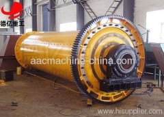
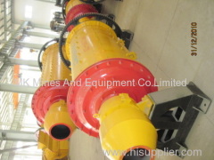
The grate ball mill is roughly composed of the cylinder, cylinder liner,big gear ring, discharging grate,and ore feeding device. Except there is a discharging grate plate installed at the discharging end, all the other is similar with the overflow ball mill. The grate ball mill discharging cover head and grate plate have the structure as the drawing: grate liner, bearing inner cover, hollow shaft, dustpan liner, central liner, rib and wedge block. In the head cover of the hollow shaft of the discharging end, it has bearing inner cover and discharging grate installed and the later is made from central liner, grate liner and dustpan liner etc. There are eight radial rib casted on the inner wall of the head cover, which divide the head cover into 8 fan rooms. There installed the dustpan liner inside each fan shape room, with the bolt fixed on the end cover. Finally the grate plate are installed on each fan room shaped by the dustpan liner. The grate liner has two kinds of structure: one is the group formed by two pcs, pressed by the wedge block, which get fixed tightly on head cover with the bolt getting through the rib. The central part are supported by the central liner to prevent them from declining and dropping off. The other kind is get two pcs into one block, fixing with bolt directly. The central liner is star shape, formed by two block, tightened on the rib with the bolt. Sepcifications
Technical Task
|


