ARM M3 LPC1768 Development Board for LPC series
| Min. Order: | 1 Bag/Bags |
|---|---|
| Payment Terms: | Paypal, T/T, WU |
| Supply Ability: | 1000 |
| Place of Origin: | Guangdong |
Company Profile
| Location: | Shenzhen, Guangdong, China (Mainland) |
|---|---|
| Business Type: | Manufacturer |
Product Detail
| Means of Transport: | Ocean, Air, Land |
|---|---|
| Production Capacity: | 1000 |
| Delivery Date: | 1-2days |
Product Description
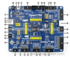
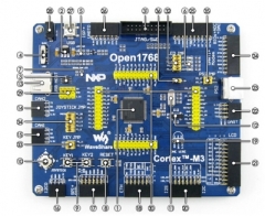
ARM Cortex M3 LPC1768 Development Board for NXP LPC series
Open1768 is an ARM Cortex-M3 development board that features an LPC1768
device as the microcontroller. It supports further expansion with
various optional accessory boards for specific application. The modular
and open design makes it the ideal for starting application development
with ARM Cortex-M3 microcontroller.
LPC1768FBD100: the high performance ARM Cortex-M3 LPC MCU which features:
Core: Cortex-M3 32-bit RISC
Operating Frequency: 100MHz Max
Operating Voltage: 2.4-3.6V (3.3V typical)
Package: LQFP100
I/Os: 70
Memories: 512kB Flash, 64kB RAM
Communication Interfaces: 2 x SPI, 2 x SSP, 4 x UART, 3 x I2C, 1 x I2S, 6 x PWM, 8 x ADC, 1 x DAC
Debugging/Programming: supports SWD interfaces, supports ISP through UART
AMS1117-3.3: 3.3V voltage regulator
LM3526-L: USB power switch and over-current protection
Power switch
Power indicator
LEDs: convenient for indicating I/O status and/or program running state
USB communication indicator
Reset button
User keys: for I/O input test and/or program control
Joystick: five positions
12M crystal oscillator: enables the MCU run at 48M frequency by frequency multiplication
32.768K crystal oscillator: for internal RTC, also supports clock calibration
USB HOST port: for connecting USB flash drive, etc.
CAN2 interface: communicates with accessory boards which feature the CAN device conveniently
CAN1 interface: communicates with accessory boards which feature the CAN device conveniently
I2C0 interface: easily connects to I2C peripherals such as I/O expander (PCF8574), EEPROM (AT24Cxx), etc.
SPI0 | SPI1 interface: for connecting SPI peripherals, such as DataFlash (AT45DBxx), SD card, MP3, etc.
Ethernet interface: easily connects the MCU to ethernet network by using an additional ethernet module, such as DP83848 Ethernet Board, etc.
ONE-WIRE interface: easily connects to ONE-WIRE devices (TO-92 package), such as temperature sensor (DS18B20), electronic registration number (DS2401), etc.
I2S interface (including I2C1, I2C2 interfaces): easily connects to I2S and/or I2C peripherals such as Stereo Audio Device (UDA1380), FRAM (FM24CLxx), etc.
LCD interface: combined with an 8-bit to 16-bit adapter, supports connecting the 3.2 inch multi-color touch screen LCD (the adapter and LCD are included in Package A/B)
UART2 | UART3 interface: for connecting UART peripherals, such as RS232, RS485, USB TO UART, etc.
PS/2 interface: easily connects to PS/2 keyboard and/or mouse
Modem interface (including UART1 interface): for connecting Modem and/or UART peripherals, such as RS232, RS485, USB TO UART, etc.
8 I/Os interface (including 3-ch AD, 1-ch DA)
for connecting accessory boards which using I/O control, such as 8 Push Buttons, Motor, etc.
also integrates AD/DA function for AD/DA testing
ISP interface (including UART0 interface): for connecting ISP modules and/or UART peripherals, such as RS232, RS485, USB TO UART, etc.
USB port: communicating with PC
5V DC jack
5V/3.3V power input/output: usually used for power output, and/or common ground with other application board
MCU pins connector: all the MCU pins are accessible on expansion connectors for further expansion
JTAG/SWD interface: for debugging/programming
LEDs jumper
User keys jumper
Joystick jumper
PS/2 jumper
short the jumper to connect to I/Os used in example code
open the jumper to connect to other custom pins via jumper wires
VBAT selection jumper
short the jumper to use system power supply
open the jumper to make it possible to connect the VBAT to external power, such as battery
For jumper 32-35: