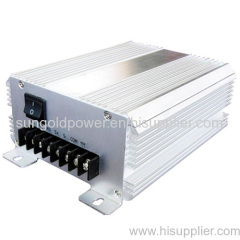
600W Wind Charge Controller / wind regulator For 12V Wind Turbine Generator
| Min. Order: | 1 Piece/Pieces |
|---|---|
| Payment Terms: | L/C, T/T, paypal |
| Place of Origin: | Guangdong |
Company Profile
| Location: | Shenzhen, Guangdong, China (Mainland) |
|---|---|
| Business Type: | Manufacturer |
| Main Products: | Power Inverter, Pure Sine Inverter, Solar Inverter, Grid Tie Inverter, Uninterruptible Power System (UPS) |
Product Detail
| Means of Transport: | Ocean, Air |
|---|---|
| Brand Name: | http://www.sungoldpower.com/ |
| wind charge controller: | wind regulator |
| Delivery Date: | 10-30 |
Product Description
The controller user's manual is suitable for 600W 12V wind turbine generator system.
1 Automatic dump load while the wind turbine generator overload.
2 Batteries overcharge protection.
3 Protect cable connect to batteries inverse.
4 Protect batteries charge to solar panel. at night
5. Protect electric shock.
Technical specifications :
Model | SG-W600 |
Rated voltage(V) | 12V |
Rated current of wind-generator(A) | 37A |
Battery over discharge protection voltage | 10.5V |
Battery over discharge recovery voltage | 11.5V |
Final charge voltage(V) | 14.4V |
Floating voltage(V) | 13V |
Recover time of braking | 30min |
Allowable ambient temperature (℃) | -2040 |
Dimension(mm) | 208x140x74 |
Weight(g) | 1500g |
1.Installing steps
1.1 Panels:
1.1.1 Terminals in accordance with the upper part of the label, the right equipment connected to cable:
W1\W2\W3:Input terminals of wind turbine generator (Regardless of sequence);
S+:Means nothing S-:Means nothing B+:Batteries + B-:Batteries -
DC+:Means nothing -1 :Means nothin-2 :Means nothing
1.2 Installing steps
1.2.1Controller based on its protection level, housed in indoor and outdoor drying, ventilation, the controller may not be around the inflammable and explosive materials
1.2.2 Controller should be mounted vertically, hanging solid.
1,2,3 Unloading an external device, due to unloading, the equipment surface temperature will exceed 85 ℃, must be firmly placed on the location where not to be touched easily, meanwhile to maintain a well-ventilated, non-flammable, explosive goods.
1.2.4 Before wiring, to put the first wind turbine brakes manually switch to the ""position, when wiring to prevent electric shock accidents caused by running generators.
1.2.5 Check the wiring correct, to put the wind turbine brakes manually switch to the "O" position, equipment into operation
Security Warning: the boot before the battery must first access controller may not be the case without the battery running generator, or generating units and the controller will cause damage!
1.3 Running state, indicator function setting
1.3.1 Running indicators
Controller in operation mode, the indicator will show the different status of the operation of equipment, detailed in the table below:
Internal dump load | State | Explanation |
L1\L2\L3(Green) | Lights | Full battery capacity |
L1\L2 (Green) | Lights | Normal battery capacity |
L1 (Green) | Lights | Low battery capacity |
L1 (Green) | Blinks | Battery exhausted |
Lights | Wind turbine generator is working | |
≈ (Red) | Lights | Dump load |
Lights | Means nothing | |
Lights | Means nothing |
2.0 Notes
2.1 Ordering Information
2.1.1 Order should be detailed description of equipment configuration requirements, such as: generator sets parameters, the choice of external dump loading devices, protective grading, as well as overload protection.
2.1.2 Use under special conditions, can be customized in accordance with the usage conditions of users.
2.2 Installation Notes
2.2.1 Before accessing controller to confirm the system equipment, such as, wind turbine, batteries, lightning protection devices, cable selection configuration is correct, accurate installation.
2.2.2 Check-to-ground insulation resistance of equipment should be in line with the wind / light generating system of technical requirements.
2.2.3 Installation, disassembly, repair equipment, wind turbine will be sure to manually switch the brake to the "|" position.
3.0 After-sales service
3.1 Customers in the procurement, use, or for advice on the quality of this product can contact the designated distributors or with the company.

