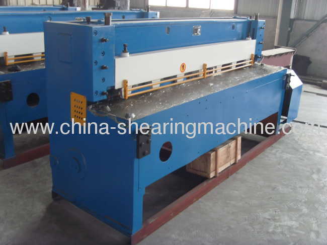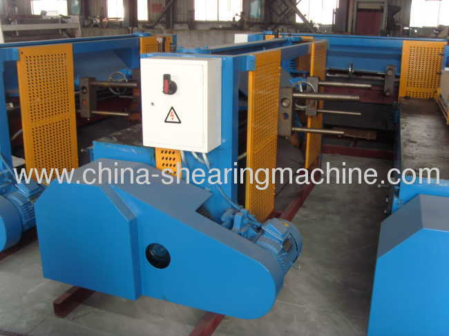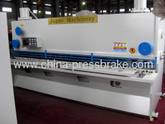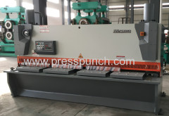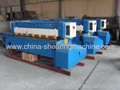
guillotine shearing machine for thin steel sheet
8160.0~15565.0 USD
| Min. Order: | 1 Set/Sets |
|---|---|
| Trade Term: | FOB |
| Payment Terms: | L/C, T/T |
| Supply Ability: | 30/set |
| Place of Origin: | Jiangsu |
Company Profile
| Location: | Nantong, Jiangsu, China (Mainland) |
|---|---|
| Business Type: | Manufacturer |
| Main Products: | Shearing Machine, Bending Machine, Plate Rolling Machine, Section Bending Machine, Hydraulic Ironworker |
Product Detail
| Model No.: | QC11-6x2500 |
|---|---|
| Means of Transport: | Ocean, Land |
| Design: | Guillotine design |
| System: | SNC-T10 NC System |
| Motor: | Siemens |
| All electrical parts: | Siemens or Schneider |
| Hydraulic system: | China famous |
| Power: | 7.5KW |
| Cutting thicknesss: | 6mm |
| Cutting width: | 2500mm |
| Cutting angle: | 2° |
| Production Capacity: | 30/set |
| Packing: | Covering with colour cloth,with steel tray |
| Delivery Date: | 25-45 workdays |
Product Description
Product name:mechanical guillotine shears,shearing machine
Model:Q11-6x2500 guillotine shearing machine
1) This machine is used for the shear sheet metal in line, metal materials should be tensile strength of less than 450 N/mm2, non-metallic material including rubber, plastics,when cut hot plate temperature should below 50 °C, The machine can make only intermittent shear in full load, if tensile strength is higher , shear thickness should be reduced.
2) The machine is applicable to uncoiling, leveling, shearing,workshop of production line for plate processing
3) The machine base is steel- welding , the structure is compact, good rigidity.
4) Track of blade movement is precision casting copper,less friction
5) Upper guide can adjust until achieve a good shear section, below blade can adjust via welding screw make the cutting mouth smooth
6) Feeding devices use spring pressure , the clamps have mat piece, pressure force is big, and not easy to damage the sheet metal surface.
7) The machine iuse completely independent closed gear box transmission system, move directly connection with main axil, compact structure, gear have good lubrication, low noise and long life.
8) The machine equipped with pneumatic clutch device, high friction, long service life, clutch speed is high so that improve the shearing speed.

1\The use and the main traits of the machine
1.1 the use of the machine
This machine is widely used in the industries such as machine manufactures, car manufacture factories, and stainless plate upholstering etc. to shear the thin plates. The machine works in the course of nature when it fulfils the conditions as follows:
a\the limiting tensile strength of plate metal  .
.
b\the thickness of the plate is about  .
.
c\the temperature of the plate is less than 50 ℃.
d\when the tensile strength of the plate is higher, the plate thickness should be reduced accordingly.
e\when working under full load, the machine can only be use to shear by fit and by start.
1.2 the main features of the machine
1.2.1 The type of this machine adopts one side open transmission, the structure is close, and the machine is safe and beautiful.
1.2.2 The knife beam is jointed by steel plate, the strength is high, the weight is light, and the shearing accuracy is higher.
1.2.3 The press of the hold-down is high and well-proportioned, it adopts non-metal materials, so the noise is low and it won't hurt the surface of the work-piece. And the machine works placidly because the press of the hold-down reacts as the equilibrant.
1.2.4 the machine has front gauge and back gauge, so it is convenient for you to use.
2\basic technical data
Main technical data
No | Name | Value | Unit | Remark | |
1 | Plate thickness | 6 | mm | ||
2 | Plate length | 2500 | mm | ||
3 | Tensile strength of plate | 160 | kg/mm2 | ||
4 | Max shearing number | 24 | n/min | ||
5 | Press material pressure | 450 | kg | ||
6 | Stroke number of top blade | 56 | n/min | ||
7 | Ram stroke distance | 65 | mm | ||
8 | Shearing angle | 2° | |||
9 | Blade length | 2600 | mm | ||
10 | Flywheel speed | 228 | r/min | ||
11 | Distance between columns | 1435 | mm | ||
12 | Max length of back gauge | 650 | mm | ||
13 | Max length of front gauge | 1000 | mm | ||
14 | Height of worktable | 960 | mm | ||
15 | Distance between press material board and blade edge | 36 | mm | ||
16 | Motor | Type | Y132M-4 | ||
Power | 7.5 | kw | |||
Speed | 1460 | r/min | Synchronous rotating speed | ||
3\the sketch map of the machine's transmission

picture 1-1
Motor (01) is fixed behind the left-hand upright, it drives the start shaft by belt, and there is a gear (03) at the other end of the shaft, and the gear (03) is in contact with the gear (04) fixed in the spindle. The gear (04) drives the driving spindle (06) because of the rolling key and shifter (05). There are two eccentric wheels fixed on the spindle. The ram begins to move up and down to shear the plate when the eccentric wheel drives the connecting rod.
4\structure information guide
4.1 frame, front gauge, side gauge
The frame is made of right-hand upright, left-hand upright, table, top beam and bottom beam. And the holistic structure's rigidity is good. The frame has front bracket and side gauge device. The front gauge can move in the T-groove in the table and front extension arm to adjust the dimension. The side gauge is adopted to shear the plates in the shape of right-angle.
4.2 back gauge
The back gauge device is used to shear a passel of plates of the same length, so the efficiency is high and the size is precise. It is made of extension arms, gear shaft, fender, hand wheel shaft etc. When using it, please unlock the locked handgrip, rotate the hand wheel, then you can get the required dimension, and you should lock the handgrip after the adjustment.
4.3 clutch
This machine adopts rolling key clutch device. When you are preparing to shear, please jam on the foot switch, so the electromagnet adsorbs the iron, and the rolling key shifter departs from the rolling key clutch because of the spring, then the rolling key connects the clutch, the spindle begins to rotate, the machine begins to shear.
4.4 hold-down device
The device is used to impact the shearing plate on the table firmly, to avoid moving or jumping, and so as to make sure of the shearing precision.
The hold-down plate is fixed between the two guide ways, and can move up and down. The guide ways is connected to the two uprights, and the spring rod is fixed on the top of the hold-down plate. The oppressive spring is covered on the rod. When the ram moves up, the hold-down plate moves up synchronously. When the ram moves down, the top plate presses the spring and the hold-down plate so the shearing plate is fixed firmly. The pressure is higher and higher when the ram moves down during shearing. And by the time, the hold-down springs can also balance the ram, so that the ram moves steadily.
4.5 brake
The machine adopts band brake. The brake is fixed on the left end of the spindle. The brake is used to stop the knife beam on the top point position after shearing. And it provides the moment of friction force during shearing to counteract the unbalanced moment of force caused by the weight of the knife beam and hold-down springs, so that the machine can work steadily. The moment caused by the brake can be adjusted by the nuts on the top of the brake springs.
