
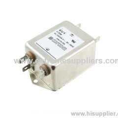
F7298 TE 6V1 Corcom 6609040-2 1609040-2
| Min. Order: | 1 PIECE |
|---|---|
| Payment Terms: | L/C, D/A, T/T |
| Supply Ability: | 12345678 |
| Place of Origin: | Shanghai |
Company Profile
| Location: | Shanghai, China (Mainland) |
|---|---|
| Business Type: | Manufacturer, Trading Company, Agent, Distributor/Wholesaler, Service |
| Main Products: | Corcom Filter CU Series (1-15 Amp), EMI Filter Corcom Accessory Outlet Filter(EBF Series ), TE Corcom/RFI Power Line Filters/B Series (1-30 Amp), RFI Power Line Filters EC Series (1-10 Amp) |
Product Detail
| Model No.: | 6V1 |
|---|---|
| Means of Transport: | Ocean, Air, Land |
| Brand Name: | TE |
| Production Capacity: | 12345678 |
| Packing: | 120PIECE/BOX |
| Delivery Date: | 35days |
Product Description
V and W Series
Both the V and W series are effective to control
emissions in equipment using SCR and T2L circuits for compliance with FCC Part 15,
V Series
- Offers an N = 3 ("T") Line to Ground impedance to common mode and an N = 5 "Dbl. Pi") impedance for Line to Line differential mode interference
- Designed for susceptibility use when equipment impedance at RF frequencies is low
- Offers an N = 4 ("Dbl. L") Line to Ground impedance for common mode and an N=5 ("Dbl. Pi") impedance for Line to Line differential mode interference
- Designed for use when equipment impedance at RF frequencies is high
- Two stage construction provides excellent suppression at high frequencies

Available Part Numbers
Click on any part number for 3D CAD models, customer drawings, distributor stock status and eCommerce Links.
| 3VV1 | 3VW1 |
| 6VV1 | 6VW1 |
| 10VV1 | 10VW1 |
| 20VV1 | 20VW1 |
| 20VV6 | 20VW6 |
| 20VW7 |
| Maximum leakage current, each Line to Ground: | ||
| @ 120 VAC 60 Hz | 0.5 mA | |
| @ 250 VAC 50 Hz | .82 mA | |
| Hipot rating (one minute): | ||
| Line to Ground | 2250 VDC | |
| Line to Line | 1450 VDC | |
| Operating Frequency: | 50 / 60 Hz | |
| Rated voltage (max.): | 250 VAC | |
| Rated Current: | 3A to 20A | |
| 20A models VDE approved to 16 Amps | ||
| Operating Ambient Temperature Range (at rated current Ir): | ||
| -10°C to +40°C | ||
| In an ambient temperature (Ta) higher than +40°C the maximum operating current (Io) is calculated as follows: Io = Ir √(85-Ta)/45 | ||
V Series

W Series (3, 6 & 10A)

W Series (20A)

Case Styles
V1 / W1 (3, 6 & 10A)

| Typical Dimensions: | ||
| Line/Load Terminals(4): | .250 [6.3] with .07 [1.8] Dia. hole | |
| Ground Terminal(1): | .250 [6.3] with .07 x .16 [1.8 x 3.8] slot | |
| Mounting Holes (2): | .188 [4.75] Dia. | |