
F7128 Corcom 5VB2 TE 1609021-8 6609024-8
| Min. Order: | 100 Piece |
|---|---|
| Payment Terms: | L/C, D/A, T/T |
| Supply Ability: | 1000000 |
| Place of Origin: | Shanghai |
Company Profile
| Location: | Shanghai, China (Mainland) |
|---|---|
| Business Type: | Manufacturer, Trading Company, Agent, Distributor/Wholesaler, Service |
| Main Products: | Corcom Filter CU Series (1-15 Amp), EMI Filter Corcom Accessory Outlet Filter(EBF Series ), TE Corcom/RFI Power Line Filters/B Series (1-30 Amp), RFI Power Line Filters EC Series (1-10 Amp) |
Product Detail
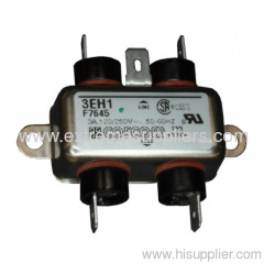
| Model No.: | 3EH1 |
|---|---|
| Means of Transport: | Ocean, Air, Land |
| Production Capacity: | 1000000 |
| Packing: | 25/BOX |
| Delivery Date: | 35 |
Product Description
| Power Inlet Line Filter for Medical Equipment | |||||||||||||||||||||||||||||||||||||||||||||||||||||||||||||||||||||||||||||||||||||||||||||||||||||||||||||||||||||||||||||||||||||||||||||||||||||||||||||||||||||||||||||||||||||||||||||||||||||||||||||||||||||||||||||||||||||||||||||||||||||||||||
UL Recognized CSA Certified VDE Approved 15A versions are tested by Underwriters Laboratories to US and Canadian requirements and are VDE approved at 10A, 250VAC Catalog Data SheetPrinter friendly version | |||||||||||||||||||||||||||||||||||||||||||||||||||||||||||||||||||||||||||||||||||||||||||||||||||||||||||||||||||||||||||||||||||||||||||||||||||||||||||||||||||||||||||||||||||||||||||||||||||||||||||||||||||||||||||||||||||||||||||||||||||||||||||
H Series
Ordering Information * IEC 60320-1 C14 inlet mates with C13 connector Available Part Numbers Click on any part number for 3D CAD models, customer drawings, distributor stock status and eCommerce Links.
| Specifications
Electrical Schematic Accessories GA400: NEMA 5-15P to IEC 60320-1 C13 line cord | ||||||||||||||||||||||||||||||||||||||||||||||||||||||||||||||||||||||||||||||||||||||||||||||||||||||||||||||||||||||||||||||||||||||||||||||||||||||||||||||||||||||||||||||||||||||||||||||||||||||||||||||||||||||||||||||||||||||||||||||||||||||||||
| Case Styles | |||||||||||||||||||||||||||||||||||||||||||||||||||||||||||||||||||||||||||||||||||||||||||||||||||||||||||||||||||||||||||||||||||||||||||||||||||||||||||||||||||||||||||||||||||||||||||||||||||||||||||||||||||||||||||||||||||||||||||||||||||||||||||
H1 (Chassis Mount)
H3 (Chassis Mount)
H4 & H4C
H9
| H5
H8
Recommended Panel Cutouts Note 1: H4, H4C and H8 allow for front or back mounting Note 2: H5 and H9 allow for back mounting only Case Dimensions
| ||||||||||||||||||||||||||||||||||||||||||||||||||||||||||||||||||||||||||||||||||||||||||||||||||||||||||||||||||||||||||||||||||||||||||||||||||||||||||||||||||||||||||||||||||||||||||||||||||||||||||||||||||||||||||||||||||||||||||||||||||||||||||
Performance Data
| |||||||||||||||||||||||||||||||||||||||||||||||||||||||||||||||||||||||||||||||||||||||||||||||||||||||||||||||||||||||||||||||||||||||||||||||||||||||||||||||||||||||||||||||||||||||||||||||||||||||||||||||||||||||||||||||||||||||||||||||||||||||||||
| Dimensions are in inches and millimeters unless otherwise specified. Values in italics are metric equivalents. Dimensions are shown for reference purposes only. Specifications subject to change. | ||||||||||||||||||||||||||||||||||||||||||||||||||||||||||||||||||||||||||||||||||||||||||||||||||||||||||||||||||||||||||||||||||||||||||||||||||||||||||||||||||||||||||||||||||||||||||||||||||||||||||||||||||||||||||||||||||||||||||||||||||||||||||
Corporate Information
- Who We Are
- Investors
- News Room
- Careers
Quick Links
- Check Distributor Inventory
- Cross Reference
- Find Documents & Drawings
- Product Compliance Support Center
- Site Map
Customer Support
- Email or Chat with Us
- Find a Phone Number
- Search Knowledge Base
- Manage Your Account