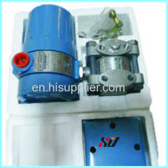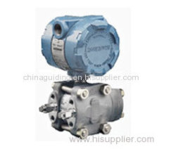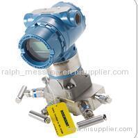
Rosemount 1151 Pressure transmitter
| Payment Terms: | L/C, T/T |
|---|
Company Profile
| Location: | China (Mainland) |
|---|---|
| Business Type: | Manufacturer, Trading Company |
Product Detail
| Model No.: | 1151 |
|---|---|
| Means of Transport: | Ocean |
| Brand Name: | Rosemount |
Product Description
With over five million transmitters installed worldwide, the Rosemount 1151 continues to offer industry leading
value. Changing customer needs and new technologies have driven product improvements, while advanced
manufacturing and testing processes have guaranteed product quality. Even today, the Rosemount 1151 is
world-reowned for proven field reliability and longevity.
Proven field performance and reliability
For over 35 years, the 1151 has provided the process
control industry with unsurpassed service and
reliability in even the harshest of environments. The
lasting customer preference results from a
combination of advanced technology, and a tradition
of field proven performance.
Commitment to continuous improvement
Through ongoing focus on continuous improvement,
±0.075% reference accuracy has been accomplished
as a result of manufacturing and engineering
enhancements. In addition, Smart electronics offer
rangeability to 50:1, reducing the number of
transmitters to specify, procure, and carry in
inventory. A modular design allows interchangeable
mechanical and electrical components, providing
backward and forward compatibility.
Application flexibility
The 1151 offers a variety of configurations for
differential, gage, absolute and liquid- level
measurements including integrated solutions for
pressure, level, and flow. High pressure models allow
static line pressures up to 4500 psi (310 bar).
Multiple wetted materials, as well as alternative fill
fluids ensure process compatibility. Smart, analog
and low-power electronics are available to meet
specific application requirements.
PERFORMANCE SPECIFICATIONS
(Zero-based calibrated ranges, reference conditions, silicone oil
fill, 316 SST isolating diaphragms.)
Accuracy
Output Code S
Ranges 3 through 8, DP and GP transmitters;
Ranges 4 through 7, HP transmitters
±0.075% of calibrated span for spans from 1:1 to 10:1 of URL.
Between 10:1 and 50:1 of URL.
All other ranges and transmitters
±0.25% of calibrated span(1)
Output Code S, square root mode
Output Codes E, G, L, and M
±0.2% of calibrated span for 1151DP Ranges 3 through 5. All
other ranges and transmitters, ±0.25% of calibrated span.
Stability
Output Code S
±0.1% of URL for 2 years for DP and GP Ranges 3 through 8.
(±0.25% for all other ranges and transmitters.)
Output Codes E and G
±0.2% of URL for six months for Ranges 3 through 5. (±0.25
for all other ranges.)
Output Codes L and M
±0.25% of URL for six months
Temperature Effect
Output Code S [20 to 185 °F (29 to 85 °C)]
For DP and GP transmitter Range 4 through 8;
HP transmitter Range 4 through 7:
Zero Error = ±0.2% URL per 100 °F (56 °C)
Total Error = ±(0.2% URL + 0.18% of calibrated span)
per 100 °F; For Range 3, double the stated effects. For other
ranges and transmitters follow analog temperature
specifications (Output Code E).
Output Code E, G, L, and M
[20 to 200 °F (29 to 93 °C)]
For Ranges 4 through 0
Zero Error = ±0.5% URL per 100 °F.
Total Error = ±(0.5% URL + 0.5% of calibrated span) per 100
°F; double the effect for Range 3.
Static Pressure Effect DP Transmitters
DP Transmitters
Zero Error
±0.25% of URL for 2,000 psi (13790 kPa)
for Range 4 and 5 or ±0.5% for other ranges, correctable
through rezeroing at line pressure.
Span Error
Correctable to ±0.25% of input reading per 1,000 psi
(6895 kPa), or to ±0.5% for Range 3.
HP Transmitters
Zero Error
±2.0% of URL for 4,500 psi (31027 kPa), correctable through
rezeroing at line pressure.
Span Error
Correctable to ±0.25% of input reading per 1,000 psi
(6895 kPa).
Vibration Effect
0.05% of URL per g to 200 Hz in any axis
Power Supply Effect
Output Codes S, E, and G
Less than 0.005% of output span per volt
Output Codes L, M
Output shift of less than 0.05% of URL for a 1 V power supply
shift
Load Effect
Output Codes S, E, and G
No load effect other than the change in power supplied to the
transmitter.
Output Codes L, M
Less than 0.05% of URL effect for a change in load from
100k to infinite ohms.
Short Circuit Condition (Low Power Only)
No damage to the transmitter will result when the output is shorted
to common or to power supply positive (limit 12 V).
EMI/RFI Effect
Output shift of less than 0.1% of span when tested to SAMA PMC
33.1 from 20 to 1000 MHz and for field strengths up to 30 V/m.
Mounting Position Effect
Zero shift of up to 1 inH2O (0.25 kPa).
With liquid level diaphragm in vertical plane, zero shift of up to 1
inH2O (0.25 kPa). With liquid level diaphragm in horizontal plane,
zero shift of up to 5 inH2O (1.25 kPa) plus extension length on
extended units. All zero shifts can be calibrated out. No effect
on span.
FUNCTIONAL SPECIFICATIONS
Service
Liquid, gas, and vapor applications
Ranges
See Table 2 for ranges. Minimum span equals the upper range
limit (URL) divided by rangedown. Rangedown varies with the
output code See Table 1.
Outputs
Code S, Smart
420 mA dc, user selectable for linear or square root output.
Digital process variable superimposed on 420 mA signal,
available to any host that conforms to the HART® protocol.
Code E, Analog
420 mA dc, linear with process pressure
Code G, Analog
1050 mA dc, linear with process pressure
Code L, Low Power
0.8 to 3.2 V dc, linear with process pressure
Code M, Low Power
1 to 5 V dc, linear with process pressure
Current Consumption Under Normal Operating
Conditions (Low Power Only)
Output Code L
1.5 mA dc
Output Code M
2.0 mA dc
Zero Elevation and Suppression
Output Codes S, E, and G
Zero elevation and suppression must be such that the lower
range value is greater than or equal to the (URL) and the
upper range value is less than or equal to the (+URL). The
calibrated span must be greater than or equal to the minimum
span and less than or equal to the maximum span.
Output Code L
Zero is adjustable ±10% of URL and span is adjustable from
90 to 100% of URL.
Output Code M
Zero is adjustable ±50% of URL and span is adjustable from
50 to 100% of URL.
Span and Zero
Output Code S
Span and zero may be accessed with local adjustments or
remotely through a HART-compatible Interface.
Output Codes E, G, L, and M
Span and zero are continuously adjustable.
Power Supply
External power supply required. Transmitter operates according to
the following requirements:
Output Codes S, E
12 to 45 V dc with no load
Output Code G
30 to 85 V dc with no load
Output Code L
5 to 12 V dc
Output Code M
8 to 14 V dc.
Language Option
rosemount 1151


