Auto Signal Generator of ECU Plus
| Min. Order: | 1 Piece/Pieces |
|---|---|
| Payment Terms: | T/T, WU |
| Supply Ability: | 1000 |
| Place of Origin: | Guangdong |
Company Profile
| Location: | Shenzhen, Guangdong, China (Mainland) |
|---|---|
| Business Type: | Manufacturer |
| Main Products: | ECU REPAIR TOOL, XCAR-431, ECU Laboratorial Equipment |
Product Detail
| Means of Transport: | Air |
|---|---|
| Production Capacity: | 1000 |
| Packing: | Standard packing |
| Delivery Date: | within 3 days |
Product Description
Auto Signal Generator of ECU
I. Introduction
Auto signal generator designed under the rules by the diagnosis of auto electronic control systems and electronic circuit signal characteristics, specifically designed for the auto service technician. This instrument easy to use, supplied with cables for variety sensors. Also have the network support for auto sensors database. Used for Automotive fault diagnosis, ECU repair, EECU teaching fields, etc.
III. Instrument Features
1, Signal Characteristics Adjustment: Adjust the amplitude, frequency, phase, X + Y, waveform and other indicators, while the signal output. This is very convenience for auto ECU repair.
2, Multi-output signal: Made by high-performance microprocessors, can output 7 signals simultaneously.
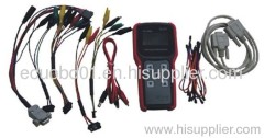
3, Human control interface: By the simple design ideas, 128*64 LCD, Bilingual display, easy to operate.
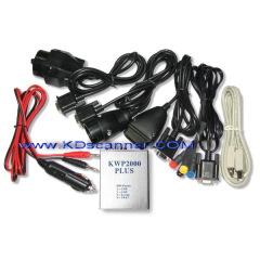
4, Cables: Supporting common sensor cables, for various models.
IV. Function Introduction
This instrument can simultaneous output sinusoidal, square-wave, X+Y signal, voltage signal, oxygen sensor signal, resistance signal and PWM signal, which includes all the common signal characteristics of automotive sensors.
1, Sinusoidal signal:
* 1--2KHz Frequency regulation;
* Signal Single-ended output to ground;
* 5Vpp--18Vpp Amplitude adjustment.
Mainly used for simulate the rotating speed, wheel speed, vehicle speed signals, which was generated by magnetic sensor.
2, Square-wave Signal:
* 1--20KHz Frequency regulation;
* Signal Single-ended output to ground;
* 5Vpp--9Vpp Amplitude adjustment.
Used for simulate the rotating speed, wheel speed, camshaft position and air-flow signals, which was generated by Hall sensor and photoelectric sensor.
3, X+Y Signal
* 1--2KHz Frequency regulation;
* 5Vpp--18Vpp Amplitude adjustment;
* 1--60 X+Y signal adjustment.
* 1--3 X+Y signal adjustment.
* 0°, 180° Phase position adjustment.
* X+Y signal outputted by Square-Ground, Sine-Ground and Sine-Couple, easy to simulate various crank signals.
* Sine-wave and Square-wave switched while Signal-Ground output.
Used for simulate the X+Y signal of Magneto electric, photo electricity and Hall sensors.
4, Voltage Signal:
* 0--5V Voltage adjustment.
* Output voltage precision 0.02V.
* Signal Single-ended output to ground
Used for simulate the voltage signal of Throttle Position, MAP and EGR Valve Position Sensors.
5, Oxygen Sensor Signal:
* The 0.1V, 0.9V Oxygen ion Dilute and Concentrate can be switched at anytime.
* Signal Single-ended output to ground
Used for simulate oxygen ion concentrate signal by kinds of oxygen sensors.
6, Resistance Signal
* Precision Multi-turn pointer potentiometer.
* 0--10K Ten loop output, MIN 22Ω
Used for output signal of coolant temperature, intake air temperature and temperature sensors. It must be realized by simulate resistance signal.
7, PWM Signal
* 2 Hz -- 999+-1 Hz Frequency can be adjusted independently.
* 1% -- 99%+-1% Duty cycle can be adjusted independently.
* Signal Single-ended output to ground.
* 9Vpp amplitude fixed output.
.....................................