SUPbearing is specialized in slewing bearing design and manufactures. slewing ring, slewing rings
Our main products are four series of slewing bearings: single-row spherical type, double-row spherical type, three-row rolling type and crossover rolling type. They are applied for all standards or non-standard specification ranged 150-4500mm.Products are sold to all over China ,and export to U.S, Germany, Australian, Singapore and other overseas countries. slewing ring, slewing rings, slewing ring bearing, slewing bearing, slewing, crossed roller bearing, double-row balls slewing ring, single-row slewing ring, single-row crossed rollers slewing ring, single-row four-point contact ball bearing slewing ring, three-row roller slewing ring
We will provide to our customers with reliable design, precise manufacture, commitment and timely service and create mutual values.
CHARACTERISTIC OF STRUCTURE,PERFORMANCE AND APPLICATION
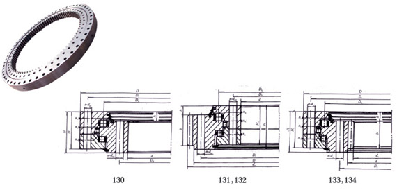
Three-row roller slewing ring has three seat-rings, which separating the upper, lower and radial raceways, via which the load of each row of the rollers maybe specified. it may bear different loads simultaneously and its load capacity is the largest one among the four models.
Owing to large size of its axle and radius, it is sturdy and especially suitable for heavy-duty machines which require large working diameter, such as buchetwheel excavators, wheeled cranes, deck cranes, port cranes, steel transporters, heavy -duty mobile cranes etc.
Notes1
1. n1-number of lurbricating holes, evenly distributed, lubricating nipple M10×1GB1152-1153-79.
2. Mounting hole n-φ, may be replaced with screw hole, tooth width b may be taken as H-h.
3. Gear force of periphery given in the table is its maximum value, nominal force of periphery is taken 1/2 of the given value.
4. The trim top coefficient of outer and inner tooth is 0.1 and 0.2, respectively.

.jpg)

.jpg)
.jpg)
