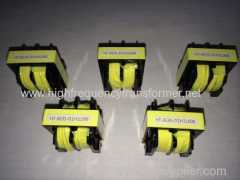
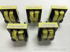
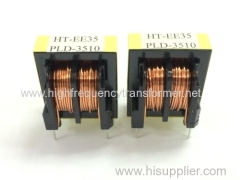
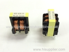
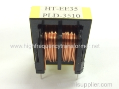
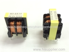
new products EE type high frequency Constant voltage transformer inn 2015
| Min. Order: | 500 PCS |
|---|---|
| Trade Term: | FOB |
| Payment Terms: | T/T |
| Supply Ability: | 3000/day |
| Place of Origin: | Guangdong |
Company Profile
| Location: | Dongguan, Guangdong, China (Mainland) |
|---|---|
| Business Type: | Manufacturer, Service |
| Main Products: | Controller EDR28 Audio Output High Frequency Transformer, Lighting Transformer And Flyback Transformer, LED Driver Dimmable Transformer, High Frequency Transformer For Power Supply, Switching Power Supply Transformers |
Product Detail
| Model No.: | EE35 |
|---|---|
| Means of Transport: | Ocean, Air, Land |
| Phase: | Others |
| Coil Structure: | Others |
| Coil Number: | Autotransformer |
| Usage: | Electronic |
| Brand Name: | Hang Tung |
| Type: | Isolation transformer |
| Band name: | Hang Tung |
| Certificate: | UL/SGS/ROHS |
| Model No: | EE35 |
| Bobbin: | EE35 vertical |
| core: | PC40 or as require |
| Usage: | ELectronics |
| Phase: | single |
| Delivery Time: | 10-15 days |
| Coil Number: | Autotransformer |
| Production Capacity: | 3000/day |
| Packing: | CASE |
| Delivery Date: | 10-15 days |
Product Description
KEY FEATURES:
EE35 for PC power transformers distribution transformer testing equipments
EE35 high-frequency transformer Features
1. window area is large,
2.It is easy to wind
3.reasonable price
4. high reliability

ELECTRICAL SPECIFICATIONS:
Model | EE35 |
Bobbin type | Vertical |
L (MAX) | 30 |
W (MAX) | 28 |
H (MAX) | 36 |
side 1 (PIN spacing) | 2 |
20 | |
side 2 PIN (PIN spacing) | 2 |
20 | |
row spacing | 22 |
PIN diameter | 0.8 |
Output power | 30 to 600 W |
Operation frequency | 20kHz-500KHz |
Operation temperature | -40℃ to +125℃ |
Storage temperature | -25℃ to +85℃ |
Storage humidity | 30 to 95% |
Remark |
Remark: The above are the common types , other types are not listed temporarily. Our company can produce all kinds of EE high-frequency transformer with different specification according to clients. Welcome to inquiry. |
Applicaton | EE35 high frequency transformer is often used for DC-DC converter, drive transformer, PC power transformers etc.
|
Price | EE35 high frequency transformer's Price range is generally between 4-10 yuan, the price depends on the degree of complexity of the process, the customer requirements for raw materials, as well as if all meet to safety certification and so on. |
1).Features:
Has a strong anti-interference, distributed capacitance, impedance, attenuation of low transmission, firm
structure,can fine-tune the inductance, etc., are widely used in fax
machines, PBX.
2). Applicable frequency range: 20 to 100kHz :
Operating frequency: higher than 200kHz
High magnetic flux and low loss magnetic materials
With low leakage inductance and high efficiency .
3).Applications:
PCB circuits, computer, TV, monitor, scanner, duplicator, mobile adapters, printer and other equipments and
instruments.
UL insulation system for Class B (130), F (155), H (180)
4). Can make other customized Ferrite transformers:
Power range: core type using N67 grade material
<5: RM4, P11/7, EF12.6 and U10
5 to 10: E (F) 16, RM5 and P14/8
10 to 20: RM6, E (F) 20, P18, U15 and EFD15
20 to 50: RM8, P22, RM10 ETD29, E25 and EFD20
50 to 100: ETD29, ETD34, RM12, P30 and EFD25
100 to 200: ETD34, ETD39, ETD44, P36, E30, E42 and EFD30
200 to 500: ETD44, ETD49 and E55
>500: ETD54, ETD59 and E65
Applications:
VCRS, Copy machine , Audio equipment , Game machines
TV sets, Microcomputer equipment
communications control equipment
printers, Terminals
good magnetic shield form itself and slight interference
Application:Transformers are also used extensively in electronic products to step-down the supply voltage to a level suitable for the low voltage circuits they contain. The transformer also electrically isolates the end user from contact with the supply voltage.
Transformer introduction:A transformer is a static electrical device that transfers energy byinductive coupling between its winding circuits. A varying current in theprimary winding creates a varying magnetic flux in the transformer's coreand thus a varying magnetic flux through the secondary winding. This varying magnetic flux induces a varying electromotive force (emf) orvoltage in the secondary winding. Transformers can be used to vary the relative voltage of circuits or isolate them, or both.
Transformers range in size from thumbnail-sized used in microphones to units weighing hundreds of tons interconnecting the power grid. A wide range of transformer designs are used in electronic and electric power applications. Transformers are essential for the transmission,distribution, and utilization of electrical energy.
Effect of frequency
Transformer universal emf equation
If the flux in the core is purelysinusoidal, the relationship for either winding between its rms voltage Erms of the winding, and the supply frequency f, number of turns N, core cross-sectional area a in m2 and peak magnetic flux densityBpeak in Wb/m2 or T (tesla) is given by the universal emf equation:[15]
If the flux does not contain evenharmonics the following equation can be used for half-cycle average voltageEavg of any waveshape:
The time-derivative term in Faraday's Law shows that the flux in the core is the integral with respect to time of the applied voltage.[25] Hypothetically an ideal transformer would work with direct-current excitation, with the core flux increasing linearly with time.[26] In practice, the flux rises to the point where magnetic saturation of the core occurs, causing a large increase in the magnetizing current and overheating the transformer. All practical transformers must therefore operate with alternating (or pulsed direct) current.[26]
The emf of a transformer at a given flux density increases with frequency.[15] By operating at higher frequencies, transformers can be physically more compact because a given core is able to transfer more power without reaching saturation and fewer turns are needed to achieve the same impedance. However, properties such as core loss and conductor skin effect also increase with frequency. Aircraft and military equipment employ 400 Hz power supplies which reduce core and winding weight.[27] Conversely, frequencies used for some railway electrification systems were much lower (e.g. 16.7 Hz and 25 Hz) than normal utility frequencies (50 – 60 Hz) for historical reasons concerned mainly with the limitations of early electric traction motors. As such, the transformers used to step-down the high over-head line voltages (e.g. 15 kV) were much heavier for the same power rating than those designed only for the higher frequencies.
Power transformer over-excitation condition caused by decreased frequency; flux (green), iron core's magnetic characteristics (red) and magnetizing current (blue).
Operation of a transformer at its designed voltage but at a higher frequency than intended will lead to reduced magnetizing current. At a lower frequency, the magnetizing current will increase. Operation of a transformer at other than its design frequency may require assessment of voltages, losses, and cooling to establish if safe operation is practical. For example, transformers may need to be equipped with 'volts per hertz' over-excitation relays to protect the transformer from overvoltage at higher than rated frequency.
One example of state-of-the-art design is traction transformers used for electric multiple unit and high speed train service operating across the,country border and using different electrical standards, such transformers' being restricted to be positioned below the passenger compartment. The power supply to, and converter equipment being supply by, such traction transformers have to accommodate different input frequencies and voltage (ranging from as high as 50 Hz down to 16.7 Hz and rated up to 25 kV) while being suitable for multiple AC asynchronous motor and DC converters & motors with varying harmonics mitigation filtering requirements.
Large power transformers are vulnerable to insulation failure due to transient voltages with high-frequency components, such as caused in switching or by lightning.


