CIPHY AND(S)AFL-4P
1
SHANGHAI CIPHY INDUSTRY CO.,LTD.
Aluminums Shell
Dual Action and Single Action Type (Spring Return)
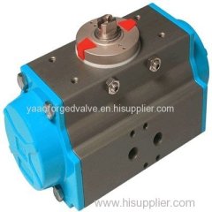
4 Piston Pneumatic Actuators
MODEL NO: AND(S)AFL-4P
THERE ARE BIG ADVANTAGES TO THINKING SMALL
WHY SMALLER IS BETTER
The sonic torque pneumatic actuator series 4×4 packs more than double the torque of conventional rack and pinion
actuator. That is because it has four pistons generating torque around a centrally located pinion. With more pistons
in the actuator, it allows their diameter to be smaller while generating higher torque. At the same time, it means the
size of the actuator can be more compact
WHY SMALLER IS FASTER
With four small cylinders each located on one of four sides of the unit and at a given air pressure,
the 4×4 produces the same torque output as double piston models using smaller diameter
pistons and a narrower pinion, the pistons travel shorter distances so that they can move faster
from one position to the next.
WHY SMALLER REDUCES AIR CONSUMPTION
The cube shape coupled with pistons traveling shorter distances minimizes size requirements
while maximizing torque output. At the same time, shorter piston travel and compact size
greatly reduces pressure requirements compared to other designs and results in reduced
energy expenditures.
WHY SMALLER MEANS LESS STRESS
It's a matter of balance. Unlike other designs that produce an off-axis thrust, the 4×4 design positions each position
around the cube so they develop thrust along their own axis. As a result, stressful piston side loading is minimized
putting less stress on seals resulting in less wear.
WHY SMALLER IS A BETTER SOLUTION
Because of the four-cylinder design, the 4×4 has many more spring combination possibilities than
double piston actuators. This means better solutions under any air pressure requirement. Each
chamber can use up to three different spring sizes which nest between the covers and pistons and
align by centering rings. Also, springs are wound in opposite directions to avoid tangles during
operation
WHY SMALLER IS STRONGER
For superior corrosion resistance, the body and covers are anodized internally and externally. Plus, they have an
external epoxy base layer and a second polyurethane paint to further reduce corrosion in demanding applications.
Extended spray wash downs do not create corrosion problems for the actuator.
Travel stops can be adjusted by four studs at the base of the actuator. The studs
are opposed from each other so no unequal forces are generated, the stop
design allows for -/+5°adjustment in both opening and closing rotations.
Mid-stroke stop points can be achieved with longer studs.
Blowout proof and Acetal support pad in body maintains proper contact of the piston racks to the
pinion at all times.
Nested spring are aligned by rings cut in the piston face and end cap. this ensures correct
orientation. with four cylinder areas, many different combinations are available allowing for
correct sizing.
CIPHY AND(S)AFL-4P
2
GENERAL FEATURES
* SonicTorque ?4×4 utilizes carbon steel pistons that allow for higher cycles because of their greater strength.
* Viton seals in the piston drive shaft also lead to higher cycles. Inside surface finish (Ra 0.4-0.6um) to minimize
friction and to maximize the life of the actuator.
* Standard applications for temperature ranges from
BUNA -4°F to 176°F -20°C to 80C
Also available Viton -4°F to 250°F -20°C to 120°C
EPDM -40°F to 176F -40°C to 80°C
* Piston bearing made of material with low friction coefficient to avoid metal to metal contact. Easily replaceable for
maintenance.
* Double lower drilling for valve mounting, and centering, according to ISO 5211/DIN 3337 standards.
* Independent bi-directional travel stop adjustment +/-5°ensuring precise positioning in all flow control services,
adjustable between 85°-95°rotation.
* Direct mounted solenoid connections according to NAMUR standards.Lower female shaft key, according to ISO
5211/DIN 3337 standards, for assembly on valves with star or square shaft.
* The lubrication carried out by the manufacturer qualifies for a minimum of 1,000,000 operations.
* Epoxy-coating is a deposit of powders on clean and sandblasted pieces. The chemical process is easily kept under
control and after coating, the pieces must be subjected to heat treatment. Epoxy painting of actuators is advised
where environment is strongly aggressive. With a normal thickness of 200/250 microns, resistance to salty fog
exceeds 1,000 hours. With the exception of certain solvents, epoxy coating resists acids and alkali, and also has a
good resistance to UV rays. In order to retain its properties, the coating must not be scratched.
* The indicator designed to remain on the actuator for continuous indication when limit switch is being used.
PARTS AND IDENTIFICATION
CIPHY AND(S)AFL-4P
3
OPERATIONS
CIPHY AND(S)AFL-4P
4
* Air supplied to port A which is connected to the center chamber forces piston apart toward end position with
exhaust air exiting at Port B (a counterclockwise rotation is obtained).
* Air supplied to Port B which is connected to the four chambers forces piston toward center with exhaust air exiting
at Port A (a clockwise rotation is obtained)
* Air supplied to port A which is connected to the center chamber forces piston apart and toward end position
compressing springs, with exhaust air exiting at Port B (a counterclockwise rotation is obtained).
* Release of air allows springs to force pistons toward center position with exhaust air exiting at Port A (a clockwise
rotation is obtained)
ACTUATION SIZING GUIDE
The seat material used, media, temperature, frequency of operation and critical application of the valve's operation
are all important factors in calculating the actuation needs of a given valve. The information provided below should
be considered as a guide only and must be adjusted according to experience and judgement. Proper actuator
selection is required to prevent valve or process equipment damage as well as proper valve operation.
For determining torque we assume that valve torque results from the friction between the ball and seats as well as
the stem and stem seals.
Valve torque
The torque requirements of Ball Valves will vary depending on several factors.
* Seat design and material
The seat friction force depends on the seat material and the applicable service factor multipliers shown in the chart
below.
* Stem seal
Torque results from the stem contact with stem seals and the type of packing materials affect torque. Stem seal
torque needs to be considered as a percentage of overall torque especially in small valve sizes.
* Service Conditions To Consider
Differential Pressure Minimum and maximum pressures
Frequency of Operation Stuck valve torque
Media Influence Slurries, dry gas, oils
Temperatures Minimum and maximums
* Media and Service Factors
To establish minimum torque requirements, multiply valve torque by the following application media and service
factor.
Double Acting Actuator (DA)
In the double acting actuators, the control pinion rotation and its reversal are
obtained by reversing the supply to the two input ports. The output torques
obtainable mainly depend on the cylinder diameter and the supply pressure;
by increasing one or both factors, the available torque also increases. As
shown in diagram A, the torque of a DA actuator is constant throughout the
entire rotation and relevant reversal. The normal advised safety factor, in
addition to the stated valve manufacturer torque, is 20%.
Select the actuator size whose torque output at given pressure exceeds the
valve torque and application factor.
CIPHY AND(S)AFL-4P
5
Spring return actuator (SR)
In these type of actuators, which utilize springs for reversing the rotation of the control
pinion, the output torque depends not only on the cylinder diameter and the supply
pressure, but also on the presence of the springs, which should be compressed to
guarantee the return. As shown in diagram B, the available torque at 0°progressively
reduces during the rotation due to the springs' compression. On the contrary, as
shown in diagram C, the torque starting from the 90°position constantly decreases
until 0°because of spring extension. Owing to the higher friction present, the safety
coefficient in his case is advised 25°.
Select the actuator whose torque output at 0°and 90°at a given air pressure exceeds
the valve torque.
Ball valve
Ball valve construction concept is based essentially on a polished ball (include a
through port) contained in two seats (upstream and downstream). The ball rotation
allows the flow, or stops the flow through the valve. Differential pressure between
upstream pressure forces the ball against the downstream seat (floating ball). In this
case, the valve torque is generated by the friction between ball and seat and also
between stem and packing. As shown in the diagram to the right, the highest torque
point is when, in presence of pressure, the valve is in the closed position, and
passes to the open position(breakaway torque).
Butterfly valve
Butterfly valve construction concept is based essentially on a disc fixed on an axis,
which in the closed position, is completely contained by the seat. The open position
is obtained when, with a rotation, the disc(through its stem) becomes parallel to the
flow. On the contrary, the closed position is obtained when the disc is perpendicular
to the flow. In the case of the butterfly valve, the torque is generated by the friction
between the disc and the seat, by the stem packing and also by the differential
pressure that forces on the disc. The highest torque point, as shown in the diagram,
is in the closed position, and only after a small rotation it is considerably reduced.
Plug valve
Plug valve construction concept is based essentially on a male (plug) contained in a
female cone (seat) . The plug provides a through port in one direction and with its
rotation into the seat the opening and closure of the valve is obtained. The torque is
usually not influenced by the flow pressure, but is generated essentially by the
friction between the seat and the plug, during the opening closing cycle. As shown
in the diagram to the right, the highest torque point is in the closed position and
remains high for the rest of the operation, because the torque is not influenced by
pressure.
CIPHY AND(S)AFL-4P
6
TORQUE RATING
CIPHY AND(S)AFL-4P
7
CIPHY AND(S)AFL-4P
8
SPRING ARRANGEMENT
CIPHY AND(S)AFL-4P
9
TECHNICAL DATA
CIPHY AND(S)AFL-4P
10
*The above indicated moving time of the actuator, are obtained in the following testcons : (1)Room Temperature.(2)
Actuator Stroke 90°(3) Solenoid Valve with orifice of 4mm and flow capacity Qn 400/L/min.(4) Inside pipe diameter
8mm, (5)Medium clean air,(6) Air supply pressure 5.5 bar(79.75psi),(7) Actuator without external resistance load.
Cautions: on the field applications when one or more of the above parameters are different, the moving time will be
different.
Accessory Top Mount NAMUR Standard VDI/VDE 3845 Bottom Mount ISO 5211
CIPHY AND(S)AFL-4P
11
CIPHY AND(S)AFL-4P
12
SHANGHAI CIPHY INDUSTRY CO.,LTD
7G-1 Building, N0.515 Yishan Rd.
Shanghai, China
TEL:+86-21-5497 5962
FAX:+86-21-5497 5963
COPYRIGHT©2004-[CIPHY]
ALL RIGHTS RESERVED.


