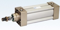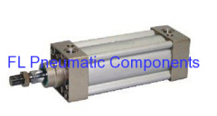
Airtac Type SI Cylinder
| Min. Order: | 100 Piece/Pieces |
|---|---|
| Payment Terms: | L/C, D/P, D/A, T/T, WU |
| Supply Ability: | 100000 |
| Place of Origin: | Zhejiang |
Company Profile
| Location: | Ningbo, Zhejiang, China (Mainland) |
|---|---|
| Business Type: | Manufacturer, Trading Company |
Product Detail
| Model No.: | SI50X100 |
|---|---|
| Means of Transport: | Ocean, Air, Land |
| Brand Name: | FL |
| Acting Type: | Double Acting |
| Fluid Medium: | Air |
| Pressure Range: | 0.05Mpa--0.8Mpa(7.3--116Psi) |
| Proof Pressure: | 1.35MPa(195psi) |
| Working Temperature: | 0--70℃ |
| Cushion: | Adjustable Cushion |
| Adjustable Cushion Stroke: | 20mm |
| Working Speed Range: | 50--800 mm/s |
| Port Size: | G1/4 |
| Origin: | China |
| Production Capacity: | 100000 |
| Packing: | In Cartons |
| Delivery Date: | Negotiable |
Product Description
Product Name: SI Seires Standard Air Cylinders
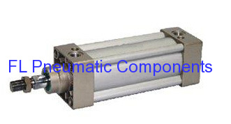
------------Airtac Type SI Standard Cylinders
Features of SI Seires Pneumatic Air Cylinders:
1. Double Acting type
2. It's tie rod cylinder
3. There are several modes of back cover so that the installation of clinder wil be more convenient
4. Various sizes of cylinders and mounting accessories for your choice
The medium used by the cylinder must be fitlered to 40μm or below
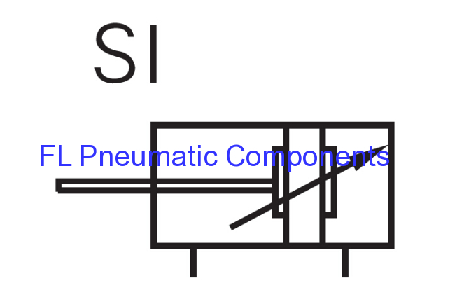
Symbol of FL Pneumatic Components-ISO15552 SI Air Cylinders:
Specification of FL Pneumatic Components-Airtac SI Air Cylinders:
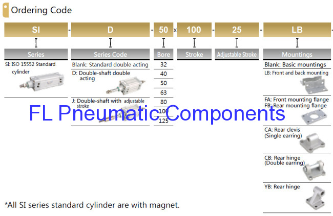
Ordering Code of FL Pneumatic Components-SI50X100 Standard Pneumatic Cylinders:
Stroke of FL Pneumatic Components-ISO 15552 Air Cylinders:
Dimension of FL Pneumatic Components SI Seies Standard Pneumatic Cylinders:
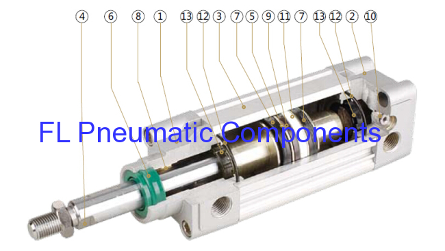
Structure of FL Pneumatic Components Airtac Type SI Pneumatic Air Cylinders:

------------Airtac Type SI Standard Cylinders
Features of SI Seires Pneumatic Air Cylinders:
1. Double Acting type
2. It's tie rod cylinder
3. There are several modes of back cover so that the installation of clinder wil be more convenient
4. Various sizes of cylinders and mounting accessories for your choice
The medium used by the cylinder must be fitlered to 40μm or below
Symbol of FL Pneumatic Components-ISO15552 SI Air Cylinders:

Specification of FL Pneumatic Components-Airtac SI Air Cylinders:
| Bore | 32 | 40 | 50 | 63 | 80 | 100 | 125 | |
| Operation Type | Double Acting | |||||||
| Working Medium | Air | |||||||
| Mounting Accessories | BASIC, FA, FB, CA, CB, LB, YB | |||||||
| Pressure Range | 0.05Mpa--0.85Mpa(7.3--123Psi) | |||||||
| Proof Pressure | 1.35MPa(217psi) | |||||||
| Working Temperature | 0--70℃ | |||||||
| Working Speed Range | 50--800 mm/s | |||||||
| Cushion | Adjustable Cushion | |||||||
| Adjustable Cushion Stroke | 20mm | 26mm | ||||||
| Port Size | G1/8 | G1/4 | G3/8 | G1/2 | ||||
Ordering Code of FL Pneumatic Components-SI50X100 Standard Pneumatic Cylinders:

Stroke of FL Pneumatic Components-ISO 15552 Air Cylinders:
| Bore | Standard Stroke | Max. Stroke | Allowable Stroke |
| 32 | 25 50 75 80 100 125 150 160 175 200 250 300 350 400 450 500 | 1000 | 2000 |
| 40 | 25 50 75 80 100 125 150 160 175 200 250 300 350 400 450 500 600 700 800 | 1200 | 2000 |
| 50 | 25 50 75 80 100 125 150 160 175 200 250 300 350 400 450 500 600 700 800 900 1000 | 1200 | 2000 |
| 63 | 25 50 75 80 100 125 150 160 175 200 250 300 350 400 450 500 600 700 800 900 1000 | 1500 | 2000 |
| 80 | 25 50 75 80 100 125 150 160 175 200 250 300 350 400 450 500 600 700 800 900 1000 | 1500 | 2000 |
| 100 | 25 50 75 80 100 125 150 160 175 200 250 300 350 400 450 500 600 700 800 900 1000 | 1500 | 2000 |
| 125 | 25 50 75 80 100 125 150 160 175 200 250 300 350 400 450 500 600 700 800 900 1000 | 1500 | 2000 |
Dimension of FL Pneumatic Components SI Seies Standard Pneumatic Cylinders:
| Bore/Symbol | A | A1 | A2 | B | C | D | E | F | G | H | I | J | K | L |
| 32 | 142 | 190 | 185 | 16 | 94 | 30 | 33 | 10 | 25 | 22 | 17 | 6 | M10 x 1.25 | M6 |
| 40 | 159 | 213 | 207 | 20 | 105 | 35 | 34 | 10 | 29.5 | 24 | 17 | 7 | M12 x 1.25 | M6 |
| 50 | 175 | 244 | 233 | 27 | 106 | 40 | 42.5 | 10 | 32 | 32 | 23 | 8 | M16 x 1.5 | M8 |
| 63 | 190 | 258 | 247 | 26 | 122 | 45 | 42 | 10 | 36 | 32 | 23 | 8 | M16 x 1.5 | M8 |
| 80 | 214 | 301 | 288 | 35 | 127 | 45 | 53 | 10 | 37 | 40 | 26 | 10 | M20 x 1.5 | M10 |
| 100 | 229 | 321 | 308 | 40 | 137 | 55 | 52 | 10 | 39 | 40 | 26 | 10 | M20 x 1.5 | M10 |
| 125 | 277 | 394 | 378 | 46 | 160 | 60 | 71 | 10 | 43.5 | 54 | 40 | 10 | M27 x 2 | M12 |
| Bore/Symbol | M | N | O | P | Q | R | S | T | U | V | W | X | Y | Z | Z1 |
| 32 | 12 | 15 | G1/8 | 5 | 3 | 6.5 | 45 | 32.5 | 12 | 10 | 28 | 4 | 46 | 58.7 | 21 |
| 40 | 12 | 17.5 | G1/4 | 7 | 3 | 7 | 52 | 38 | 16 | 13 | 33 | 4 | 53.7 | 68 | 21 |
| 50 | 12 | 20 | G1/4 | 7 | 3 | 9 | 65 | 46.5 | 20 | 17 | 38 | 4 | 65.8 | 84.5 | 23 |
| 63 | 12 | 22 | G3/8 | 8 | 5 | 9 | 76 | 56.5 | 20 | 17 | 38 | 4 | 79.9 | 99.6 | 23 |
| 80 | 15 | 23 | G3/8 | 10 | 5 | 12 | 94 | 72 | 25 | 22 | 43.5 | 5 | 101.8 | 123.8 | 29 |
| 100 | 15 | 26 | G1/2 | 10 | 5 | 14 | 112 | 89 | 25 | 22 | 47 | 6 | 125.9 | 148.9 | 29 |
| 125 | 20 | 29 | G1/2 | 10 | 5 | 14 | 134 | 110 | 32 | 27 | 53 | 7 | 156.9 | 179.6 | 40.5 |
Structure of FL Pneumatic Components Airtac Type SI Pneumatic Air Cylinders:

| No. | Name | Material |
| 1 | Front Cover | Painted Aluminum |
| 2 | Back Cover | Painted Aluminum |
| 3 | Barrel | Hard Anodised Aluminum |
| 4 | Piston Rod | Chromed Carbon Steel |
| 5 | Piston | Aluminum |
| 6 | Piston Rod Seal | Polyurethane |
| 7 | Piston Seal | NBR |
| 8 | Bearing | Non-lub Bearing |
| 9 | Magnet | Plastic |
| 10 | Cushion Screw | Brass |
| 11 | Anti-frintion Ring | PTFE |
| 12 | End Cap Seal | NBR |
| 13 | Cushion Seal | NBR |


