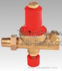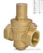
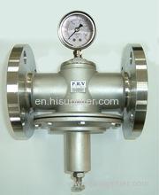
SJ200X adjustable pressure-reducing valve
| Min. Order: | 1 Piece/Pieces |
|---|---|
| Trade Term: | FOB |
| Payment Terms: | L/C, T/T |
| Place of Origin: | Zhejiang |
Company Profile
| Location: | Wenzhou, Zhejiang, China (Mainland) |
|---|---|
| Business Type: | Manufacturer, Distributor/Wholesaler |
Product Detail
| Model No.: | Hydraulic control valves |
|---|---|
| Means of Transport: | Ocean, Land |
| Brand Name: | JINGJIA |
| Delivery Date: | 30 days |
Product Description
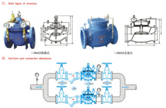
Structure and purpose
schematic diagram of installation
This valve utilizes the self energy of a medium to adjust the pipeline pressure and controls the outlet pressure of the main valve via the adjustment of the pressure reducing pilot valve. The outlet pressure does not change along with the variation of the inlet one and of the water quantity at the outlet. Reli-able sealing performance, easy installation, maintenance, debugging and check, long duration.
schematic diagram of installation
| DN(mm) | 20 | 25 | 32 | 40 | 50 | 65 | 80 | 100 | 125 | 150 | 200 | 250 | 300 | 350 | 400 | 450 | 500 | 600 | 700 | 800 | |
| L | 180 | 180 | 180 | 203 | 203 | 216 | 241 | 292 | 330 | 356 | 495 | 622 | 698 | 787 | 914 | 978 | 978 | 1295 | 1446 | 1956 | |
| PN10 | D | 105 | 115 | 135 | 145 | 160 | 180 | 195 | 215 | 245 | 280 | 335 | 390 | 440 | 500 | 565 | 615 | 670 | 780 | 895 | 1010 |
| D1 | 75 | 85 | 100 | 110 | 125 | 145 | 160 | 180 | 210 | 240 | 295 | 350 | 400 | 460 | 515 | 565 | 620 | 725 | 840 | 950 | |
| PN16 | D | 105 | 115 | 135 | 145 | 160 | 180 | 195 | 215 | 245 | 280 | 335 | 405 | 460 | 520 | 580 | 640 | 705 | 840 | 910 | 1020 |
| D1 | 75 | 85 | 100 | 110 | 125 | 145 | 160 | 180 | 210 | 240 | 295 | 355 | 410 | 470 | 525 | 585 | 650 | 770 | 840 | 950 | |
| PN25 | D | 105 | 110 | 135 | 145 | 160 | 180 | 195 | 230 | 270 | 300 | 360 | 425 | 485 | 550 | 610 | 660 | 730 | 840 | 955 | 1070 |
| D1 | 75 | 85 | 100 | 110 | 125 | 145 | 160 | 190 | 220 | 250 | 310 | 370 | 430 | 490 | 550 | 600 | 660 | 770 | 875 | 990 | |
| H | 342 | 342 | 342 | 395 | 395 | 405 | 430 | 510 | 560 | 585 | 675 | 730 | 760 | 840 | 910 | 1030 | 1135 | 1270 | 1460 | 1640 | |
| H1 | 247 | 247 | 247 | 278 | 278 | 298 | 313 | 350 | 365 | 420 | 450 | 470 | 490 | 526 | 570 | 610 | 665 | 725 | 865 | 975 | |



.jpg)
