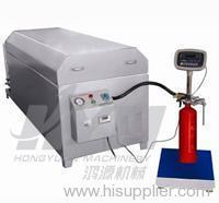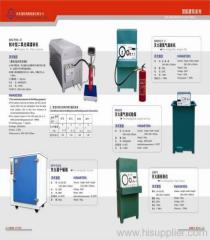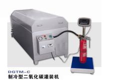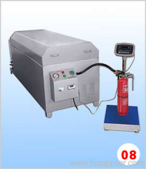
extinguisher Carbon dioxide filler
1.0~4000.0 USD
| Min. Order: | 1 Set/Sets |
|---|---|
| Trade Term: | FOB |
| Payment Terms: | L/C, T/T |
| Supply Ability: | 100set/month |
| Place of Origin: | Hebei |
Company Profile
| Location: | Shijiazhuang, Hebei, China (Mainland) |
|---|---|
| Business Type: | Manufacturer, Trading Company |
Product Detail
| Model No.: | GTM-B |
|---|---|
| Means of Transport: | Ocean, Air, Land |
| Brand Name: | HAORI |
| Production Capacity: | 100set/month |
| Packing: | wooden box |
| Delivery Date: | 15 days |
Product Description
I. General Survey
GTM-B Type filler for CO2 fire extinguisher is a special equipment for filling MT2-MT7 portable extinguishers with CO2 extinguishants automatically. It makes a comprehensive use of electronic, electric, and mechanical techniques and renders the whole filling processes safe, reliable, simple in operation, accurate in filling quantity and highly efficient.
II. Main Technical Parameters
1. Error Table for Filling Time and Quantity of the Filler
Specification Parameters Items | MT2 | MT3 | MT5 | MT7 |
Weight of extinguisher (kg) | 0 2 -0.15 | 0 3 -0.15 | 0 5 -0.2 | 0 7 -0.2 |
Filling time(s) | ≤50 | ≤60 | ≤60 | ≤90 |
2. Working Temperature and Pressure Parameters of the Thermostat of the Filler
A. Thermal uniform temperature is controlled in the range of 38℃–45℃ with a pressure of 9-10Mpa, heater power of 6KW and voltage of 380V.
B. Cold uniform temperature is controlled in the range of –5℃—5℃with a pressure of ≤7Mpa and power source voltage of 220V.
Thermal thermostat |
Console of filling |
Cold thermostat |
Source of extinguishant |
Console of filling |
Cold thermostat |
Source of extinguishant |
Console of filling |
Cold thermostat |
Source of extinguishant |
Figure 1 Schematic Diagram of GTM-B Type Filler for CO2 Fire Extinguisher
1. Terminal of the heater 2. gas cylinder 3. Sensor 4. II Character-type fixture 5. Gas outlet 6. Exit valve 7. Gas inlet A 8. Gas inlet B 9. Inlet valve A 10. Inlet valve B 11. Gas source pressure meter B 12. Mixer 13. Operating Indication Lamp 14. Power Source Indication Lamp 15. Gas Source Pressure Meter A 16. SJD-temperature Controller 17. Charge pressure indicator 18. Power Source Switch 19. T3806 Electronic Scale Indicator. 20. Control Panel for Electric Appliances 21. Charge pipe 22. Cylinder valve 23. II Character-type fixture 24. Cylinder 25. Stand of electronic scale 26. Compressor
IV. Main Structure and Functions
GTM-B Type filler for CO2 fire extinguisher is chiefly composed of filling console, thermal thermostat, cold thermostat and electronic scale.
1. Filling console is used for controlling the quantity of filling the cylinder with CO2 extinguishant. On it are mounted XMTA temperature controller, T3806 type electronic scale indictor, power source voltage indicator, GT solenoid valve and control panel for electric appliances.
Heater terminal (No.1 in Figure 1)—for heating the gas source cylinder
Gas source cylinder (No.2 in Figure 1)—changing the fire extinguisher
Sensor (No.3 in Figure 1)—for sensing the heating temperature
II character-type fixture (No.4 in Figure 1)—interface to the gas source
Gas outlet (No.5 in Figure 1)—the gas outlet of gas in the cold thermostat, connected to the console
Exit valve (No.6 in Figure 1)—opening or closing the gas outlet
Gas inlet A (No.7 in Figure 1) and Gas inlet B (No.8 in Figure 1) for connecting to gas source
Inlet valve A (No.9 in Figure 1) and Inlet valve B (No.10 in Figure 1)—opening or closing the gas inlet
Gas source pressure meter B (No.11 in Figure 1) and Gas source pressure meter A (No.15 in Figure 1)—for display of gas source pressure
Mixer (No.12 in Figure 1)—making the temperature of cold thermostat uniform
Operating indication lamp (No.13 in Figure 1)—showing the refrigerator is in operation
Power source indication lamp (No.14 in Figure 1)—showing the refrigerator is energized
SJP-1 Temperature Controller (No.16 in Figure 1)—intelligent regulation of temperature
Charge pressure indicator (No.17 in Figure 1)—showing the charge pressure
Power source switch (No.18 in Figure 1)—controlling the start and suspension of refrigerating system
T3806 indicator (No.19 in Figure 1)—showing the quantity filled in the cylinder
Control panel for electric appliances (No.20 in Figure 1)—for operating and controlling the completion of all jobs.
Charge pipe (No.21 in Figure 1)—for connecting the console of filling and the cylinder valve (No.22 in Figure 1)—controlling the outlet and inlet of cylinder gas.
II character-type fixture (No.23 in Figure 1)—for clipping the filled cylinder
Cylinder (No.24 in Figure 1)—the filed cylinder
Stand of electronic scale (No.25 in Figure 1)—for sensing the weight of cylinder
Compressor (No.26 in Figure 1)—completing the refrigeration operation
2. Thermal thermostat is composed of a water bath, a support and a heater for thermal uniform temperature treatment of CO2 extinguishant to meet the requirement of filling technology.
3. Cold thermostat is composed of box body, stainless steel liner, evaporator, refrigerating compressor, temperature controller and pressure indicator. It can reduce the temperature of CO2 fire extinguishant by mechanical refrigeration, which will meet the requirement of filling technology.


