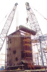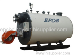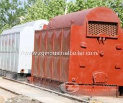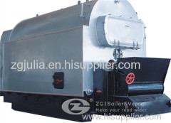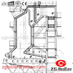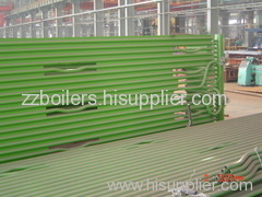
Coal-fired Outer Casing Boiler Tube
| Min. Order: | 1 Set/Sets |
|---|---|
| Payment Terms: | L/C, T/T |
| Supply Ability: | 100 Set/Sets per Year |
| Place of Origin: | Henan |
Company Profile
| Location: | Zhengzhou, Henan, China (Mainland) |
|---|---|
| Business Type: | Manufacturer, Trading Company, Agent, Distributor/Wholesaler, Service, Association, Other |
| Main Products: | Waste Heat Boiler, Carbon Kiln Waste Heat Boiler, Boilers, Glass Kiln Waste Heat Boiler, Boiler |
Product Detail
| Means of Transport: | Ocean |
|---|---|
| Fuel: | Coal-fired |
| Output: | Steam |
| Usage: | Industrial |
| Structure: | Water/fire Tube |
| Pressure: | Low Pressure |
| Production Capacity: | 100 Set/Sets per Year |
| Packing: | standard export package |
| Delivery Date: | 3 months |
Product Description
Coal-fired Outer Casing Boiler Tubes that can meet the customer's requiremen has the features of small occupation,quick pressure and high efficiency.
- SiO2 53.52 [%]
- Fe2O3 8.00 [%]
- Al2O3 16.24 [%]
- TiO3 1.05 [%]
- MnO 0.06 [%]
- CaO 7.75 [%]
- Na2O 0.11 [%]
- SO3 0.172 [%]
Coal-fired Outer Casing Boiler Tubes Oblique horizontal conveyor
Coal-fired Outer Casing Boiler Tubes The final (horizontal) part of the oblique-horizontal conveyor should be extended for about 10 m, in order to provide charging of the bunker for the new boiler ( alongside with the reconstruction of the reversible conveyor, too), as well as bunkers for the existing two boilers ( drawing no.6)
For wet coal combustion, it is necessary to heat the air to a temperature of 150 ° C.
To prepare and provide the air the following should be scheduled:
- fresh air preheaters (2 pieces)
- fresh air fans (2 pieces)
- secondary air fan (one piece).
Fresh air preheaters should be predicted in front of the fan.
Wet slag transport devices
Slag and ash should be extinguished and chilled in wet slag transport devices (2 pieces). Capacity of these devices is 2 t /h. Each one should have a built-in crusher.
After cooling and crushing slag is delivered onto the obliquely bands and transported to a common horizontal transporter.The horizontal transporter should be extended.
Transport of slag by belt transporters should be adjusted to the existing condition.
Existing landfills for slag and ash meet both current and future needs, as it was planned and carried out in the first phase for the final state.
To separate the remaining particles of flying ash and possibly unburned coal particles after releasing of the flue gases from the boiler, electrical filter (s) should be built in. Electrical filter(s) should be placed outside the building and protected from weather conditions.
Coal-fired Outer Casing Boiler Tubes The quality and dimensions of the inbuilt material (barrels, collectors, display tubes in the membranes, economizer pipes, air heating pipes, plating ...) are defined by the boiler manufacturer or a major mechanical project.
1.1 Coal-fired Outer Casing Boiler Tubes
Fuel
Fuel
Fuel is coal-lignite from the mine Stanari, located at 25km far from the plant in Doboj. The quantity that is usually kept in the stock is the one that can meet the needs for about 30 days in the winter period.
The composition and quality of the coal according to which the further calculations will be made are the following:
| −Carbon | Cr | 28,56 | [%] |
| −Hydrogen | Hr | 2,40 | [%] |
| −Nitrogen | Nr | 2,80 | [%] |
| −Oxygen | Or | 10,58 | [%] |
| −Total sulfur | Sr | 0,15 | [%] |
| −Sulphur flammable | Srg | 0,05 | [%] |
| −Humidity | Wr | 48,54 | [%] |
| −Ash | Ar | 7,07 | [%] |
| −Lower heatingpower | Hd | 9950 | [kJ/kg] |
Elementary composition of the ash of the accepted coal is as it follows:
- SiO2 53.52 [%]
- Fe2O3 8.00 [%]
- Al2O3 16.24 [%]
- TiO3 1.05 [%]
- MnO 0.06 [%]
- CaO 7.75 [%]
- Na2O 0.11 [%]
- SO3 0.172 [%]
1.1.1Coal-fired Outer Casing Boiler Tubes Coal storage and transport
Coal storage was designed and carried out in an earlier phase for low quality coal (calorific value about 7000 kJ / kg) and with a significantly higher ash content than coal that has been used now, and for the total installed capacity of the boiler room of 116 [MW]. Coal-fired Outer Casing Boiler Tubes All the devices for coal handling at the warehouse and its removal to the bunker on the existing boilers have also been designed and made.
Coal-fired Outer Casing Boiler Tubes The whole system for transportation of the coal to the bunkers on the existing boilers is designed for the capacity of 150 [t / h].
Coal bunker(s)
Coal bunker(s) should be provided for a new boiler.. Bunkers volume should provide work of the boiler with a full load for a period of at least 6 hours. Bunker itselfshould end in its bottom with a funnel and an opening.
Coal bunker(s) should be provided for a new boiler.. Bunkers volume should provide work of the boiler with a full load for a period of at least 6 hours. Bunker itselfshould end in its bottom with a funnel and an opening.
Coal-fired Outer Casing Boiler Tubes Oblique horizontal conveyor
Coal-fired Outer Casing Boiler Tubes The final (horizontal) part of the oblique-horizontal conveyor should be extended for about 10 m, in order to provide charging of the bunker for the new boiler ( alongside with the reconstruction of the reversible conveyor, too), as well as bunkers for the existing two boilers ( drawing no.6)
Reversible moving conveyor should be extended for approximately 7.5 m that will allow filling of the bunkers for all three boilers.
Coal-fired Outer Casing Boiler Tubes Because of the extension of the horizontal part of the vertical-oblique and reverse conveyor it is necessary to extend the rails for the reversible conveyor moving.
Coal-fired Outer Casing Boiler Tubes Because of the extension of the horizontal part of the vertical-oblique and reverse conveyor it is necessary to extend the rails for the reversible conveyor moving.
1.2 Coal-fired Outer Casing Boiler Tubes
Devices and equipment accompanying the boiler
Devices and equipment accompanying the boiler
1.2.1 Firing device
Coal-fired Outer Casing Boiler Tubes Firing device according to this variant consists of two parallel cascade grids with width of 4m, active length 7.6 m, with a device for controlling the base draft.
The active area of the grid is: 60.8 m2
Heat load of the grid is: 954 kW/m2
Coal-fired Outer Casing Boiler Tubes Firing device according to this variant consists of two parallel cascade grids with width of 4m, active length 7.6 m, with a device for controlling the base draft.
The active area of the grid is: 60.8 m2
Heat load of the grid is: 954 kW/m2
Moving of the fuel along the grid is planned to be carried out with hydraulic moving of the grid lines, resulting in a tumbling and mixing of fuel on the grid.
Supplying of the primary air for combustion is zonal.
Supplying of the primary air for combustion is zonal.
1.2.2 Device for pneumatic dust firing (PDF)
Coal-fired Outer Casing Boiler Tubes Installation of this device for combustion of the small coal fractions should be provided optionally on the new boiler.
Coal-fired Outer Casing Boiler Tubes Appearing of certain quantities of tiny coal fractions is reality, and since the existing tiny fractions of fuel can burn in the existing boilers under the assumption that the PDF devices have been provided (where a special bunker for coal dust has been built), at this stage it is necessary to consider the possibility and conditions for installation of the PDF device on the new boiler. Coal-fired Outer Casing Boiler TubesThe investor will make a final decision on the installation of this part before reaching an agreement on building a new boiler.
1.2.3 Devices for preparation and air supply
For wet coal combustion, it is necessary to heat the air to a temperature of 150 ° C.
To prepare and provide the air the following should be scheduled:
- fresh air preheaters (2 pieces)
- fresh air fans (2 pieces)
- secondary air fan (one piece).
Fresh air preheaters should be predicted in front of the fan.
Fresh air preheater
Fresh air will be absorbed from the boiler room (from the environment). In front of the fresh air fan heaters that provide partially heating of the air at about 30 ° C with hot water should be scheduled. After the fresh air fan, reheating would take part in a tube heater set in the back section of the boiler at the required 150 ° C.
Fresh air will be absorbed from the boiler room (from the environment). In front of the fresh air fan heaters that provide partially heating of the air at about 30 ° C with hot water should be scheduled. After the fresh air fan, reheating would take part in a tube heater set in the back section of the boiler at the required 150 ° C.
Fresh air fans
The fans ,which will push necessary quantity for combustion of pre-heated air (at 30 ° C) through the tube air heater into the space under the grid, should be set under the boiler. Two fresh air fans should be scheduled, one for each grid. The air should be directed through sheet metal channels, which will be isolated.
Of the total required air for combustion one part (approximately 88%) should be brought into as primary air, under the grid, and the second part (about 12%) should be insufflated into the fireplace above the grids as secondary air.
The fans should have a continuous speed control regulation using a frequency converter.
1.2.4 Devices for slag and ash discharge
The sludge and ash from the ashes of the boiler should be transferred by a rail transporter in a wet slag transport device.
The sludge and ash from the ashes of the boiler should be transferred by a rail transporter in a wet slag transport device.
Railtransporter
Install two rail transporters with capacity of 1.5 [t / h].
Install two rail transporters with capacity of 1.5 [t / h].
Wet slag transport devices
Slag and ash should be extinguished and chilled in wet slag transport devices (2 pieces). Capacity of these devices is 2 t /h. Each one should have a built-in crusher.
Belt transporters
After cooling and crushing slag is delivered onto the obliquely bands and transported to a common horizontal transporter.The horizontal transporter should be extended.
Transport of slag by belt transporters should be adjusted to the existing condition.
1.2.5 Landfill for slag and ash
Existing landfills for slag and ash meet both current and future needs, as it was planned and carried out in the first phase for the final state.
1.2.6 Devices for purification and draining of water and flue gases
To separate the remaining particles of flying ash and possibly unburned coal particles after releasing of the flue gases from the boiler, electrical filter (s) should be built in. Electrical filter(s) should be placed outside the building and protected from weather conditions.
In order to achieve required under pressure in the furnace, boiler gas canals and electro filters, a fan for smoke gasses (exhauster) should be planned. The fan should have a continuous rpm control using a frequent converter.
Smoke canals (flues)
After leaving the boiler smoke gases are led to tin channels, covered with appropriate isolation, to electro-filters, and then through the exhauster to the chimney.
Chimney
To connect a new boiler, an opening has been planned and left on the chimney at the elevation +8.76 m. The existing chimney meets the needs of the new boiler (for the existing ones and a new one).
1.2. Recirculation Pump
For constant and variable warm recirculation it is necessary to plan one circulating pump for each. See drawing number 4
Electric motors of these circulation pumps should have a continuous rpm control over through frequency regulators.
For constant and variable warm recirculation it is necessary to plan one circulating pump for each. See drawing number 4
Electric motors of these circulation pumps should have a continuous rpm control over through frequency regulators.


